


Other Parts Discussed in Thread: UNIFLASH,
Hi,
I am have spent a lot of time on this and i am hoping for a more detailed answer than read the manual because i have many times or look at the example because that is what this is all based on.
I have a flash bootloader that i have written based on the boot_loader examples. i have a windows application that communicates with it and updates the firmware.
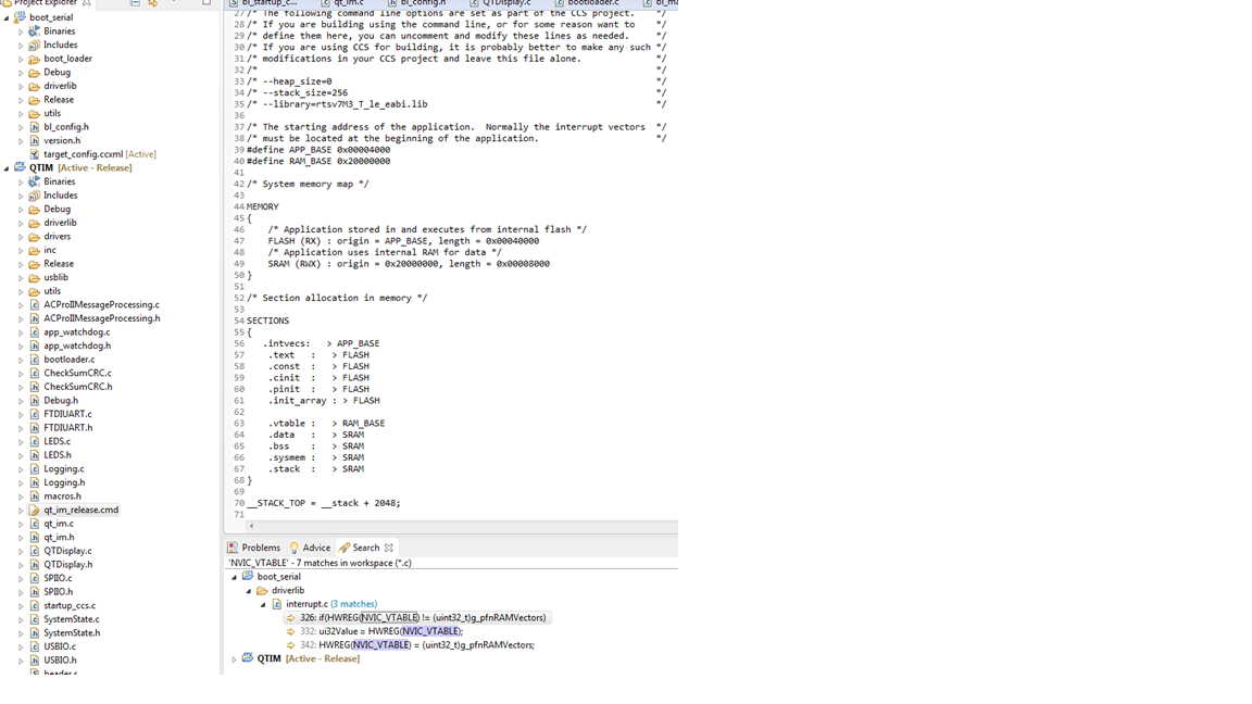
Here is the structure of my project, boot_serial is the bootloader and QTIM is the application.

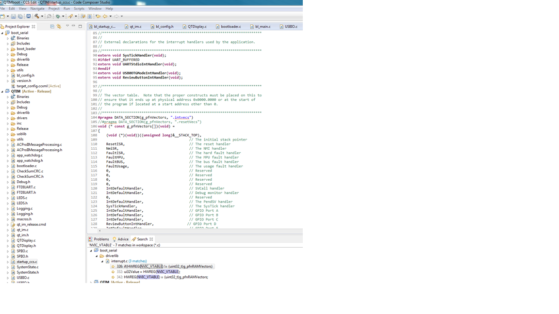
I have setup the bootloader at address 0x00000000 and the application at 0x00000000 for debug cmd and APP_BASE of 0x00004000 for the release cmd version.
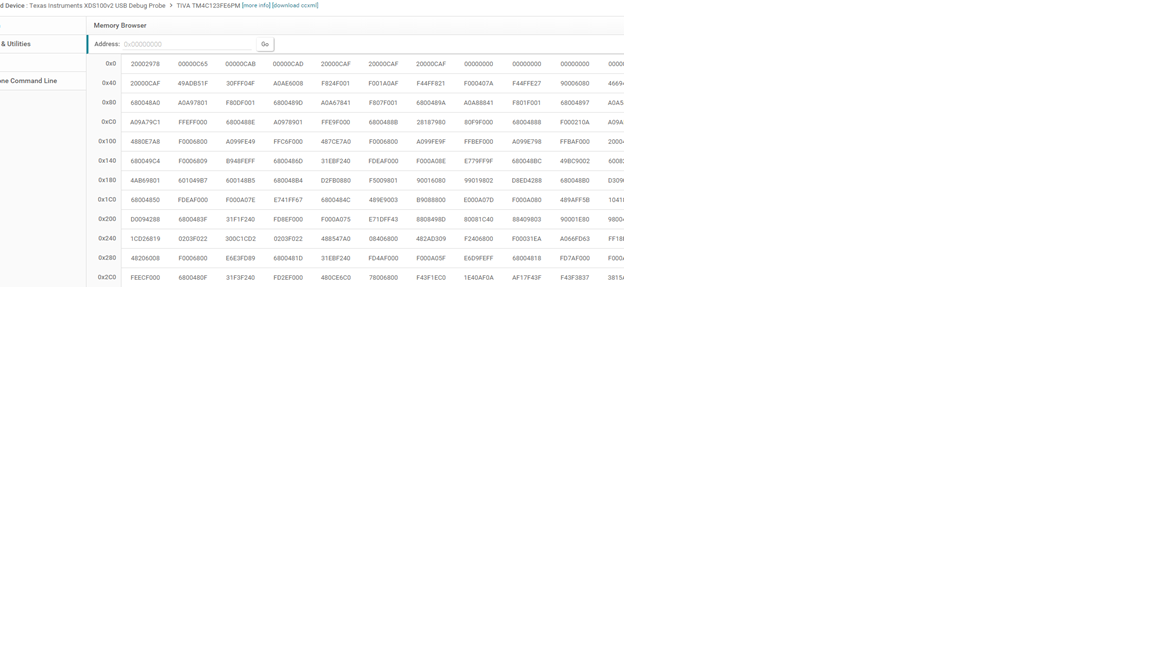
When i run my application it communicates and updates with the bootloader correctly, and when i read the memory after the update using Uniflash here is the bootloader section and application section:
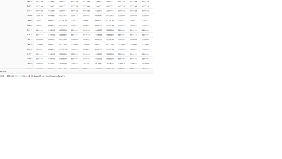
The SP in the map file for the bootloader is at the reset vector for the bootloader and the SP for QTIM is at address 4000.
After the update the board doesnt function at all. If i load the debug version of application everything runs fine. If i load the bootloader (via CCS) and flash the firmware it is all in the correct locations. The file i am flashing is the release version of application and based on the map file the addresses line up with what is written in Uniflash for the SP.
any suggestions on what the issue could be or what i should test?
Thanks,
Dustin

