This thread has been locked.

If you have a related question, please click the "Ask a related question" button in the top right corner. The newly created question will be automatically linked to this question.

CCS/EK-TM4C1294XL: MAX31855PMB1 SPI with TM4C1294XL

Part Number: EK-TM4C1294XL

Tool/software: Code Composer Studio

Hi,

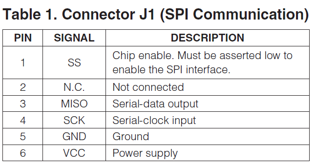
I have problem with reading temp from MAX31855MPB1 (Thermocouple). I'm using SPI communication and try to read from the MAX31855 using SSI0 port.
However, it not read any value from the MAX31855. I use debug to see if I get any data from the SPI but it stuck at

SSIDataGet(SSI0_BASE, &pui32DataRx[ui32Index]); // the code stop here and not go anywhere

Can some one help me with this. What do I need to change in my code to make it reading. Since this is the thermocouple. I only want to read value from the sensor. No Tx need for this.

//*****************************************************************************
//
// spi_slave.c - Example demonstrating how to configure SSI0 in SPI slave
//                mode.
//
// Copyright (c) 2010-2017 Texas Instruments Incorporated.  All rights reserved.
// Software License Agreement
//
//   Redistribution and use in source and binary forms, with or without
//   modification, are permitted provided that the following conditions
//   are met:
//
//   Redistributions of source code must retain the above copyright
//   notice, this list of conditions and the following disclaimer.
//
//   Redistributions in binary form must reproduce the above copyright
//   notice, this list of conditions and the following disclaimer in the
//   documentation and/or other materials provided with the
//   distribution.
//
//   Neither the name of Texas Instruments Incorporated nor the names of
//   its contributors may be used to endorse or promote products derived
//   from this software without specific prior written permission.
//
// THIS SOFTWARE IS PROVIDED BY THE COPYRIGHT HOLDERS AND CONTRIBUTORS
// "AS IS" AND ANY EXPRESS OR IMPLIED WARRANTIES, INCLUDING, BUT NOT
// LIMITED TO, THE IMPLIED WARRANTIES OF MERCHANTABILITY AND FITNESS FOR
// A PARTICULAR PURPOSE ARE DISCLAIMED. IN NO EVENT SHALL THE COPYRIGHT
// OWNER OR CONTRIBUTORS BE LIABLE FOR ANY DIRECT, INDIRECT, INCIDENTAL,
// SPECIAL, EXEMPLARY, OR CONSEQUENTIAL DAMAGES (INCLUDING, BUT NOT
// LIMITED TO, PROCUREMENT OF SUBSTITUTE GOODS OR SERVICES; LOSS OF USE,
// DATA, OR PROFITS; OR BUSINESS INTERRUPTION) HOWEVER CAUSED AND ON ANY
// THEORY OF LIABILITY, WHETHER IN CONTRACT, STRICT LIABILITY, OR TORT
// (INCLUDING NEGLIGENCE OR OTHERWISE) ARISING IN ANY WAY OUT OF THE USE
// OF THIS SOFTWARE, EVEN IF ADVISED OF THE POSSIBILITY OF SUCH DAMAGE.
//
// This is part of revision 2.1.4.178 of the Tiva Firmware Development Package.
//
//*****************************************************************************

#include <stdbool.h>
#include <stdint.h>

#include <string.h>

#include "inc/hw_memmap.h"
#include "driverlib/gpio.h"
#include "driverlib/pin_map.h"
#include "driverlib/ssi.h"
#include "driverlib/sysctl.h"
#include "driverlib/uart.h"

#define TARGET_IS_TM4C129_RA3
#include "driverlib/rom.h"

#include "utils/uartstdio.h"


//*****************************************************************************
//
//! \addtogroup ssi_examples_list
//! <h1>SPI slave (spi_slave)</h1>
//!
//! This example shows how to configure the SSI0 as SPI slave.  The code will
//! send three characters on the slave Tx then polls the receive FIFO until
//! 3 characters are received on the slave Rx.
//!
//! This example uses the following peripherals and I/O signals.  You must
//! review these and change as needed for your own board:
//! - SSI0 peripheral
//! - GPIO Port A peripheral (for SSI0 pins)
//! - SSI0Clk - PA2
//! - SSI0Fss - PA3
//! - SSI0Rx  - PA4
//! - SSI0Tx  - PA5
//!
//! The following UART signals are configured only for displaying console
//! messages for this example.  These are not required for operation of SSI0.
//! - UART0 peripheral
//! - GPIO Port A peripheral (for UART0 pins)
//! - UART0RX - PA0
//! - UART0TX - PA1
//!
//! This example uses the following interrupt handlers.  To use this example
//! in your own application you must add these interrupt handlers to your
//! vector table.
//! - None.
//
//*****************************************************************************

//*****************************************************************************
//
// Number of bytes to send and receive.
//
//*****************************************************************************
#define NUM_SSI_DATA            3

uint32_t ui32SysClock;
char str[20];


/* reverse:  reverse string s in place */
 void reverse(char s[])
 {
     int i, j;
     char c;

     for (i = 0, j = strlen(s)-1; i<j; i++, j--) {
         c = s[i];
         s[i] = s[j];
         s[j] = c;
     }
 }

 /* itoa:  convert n to characters in s */
  void itoa(int n, char s[])
  {
      int i, sign;

      if ((sign = n) < 0)  /* record sign */
          n = -n;          /* make n positive */
      i = 0;
      do {       /* generate digits in reverse order */
          s[i++] = n % 10 + '0';   /* get next digit */
      } while ((n /= 10) > 0);     /* delete it */
      if (sign < 0)
          s[i++] = '-';
      s[i] = '\0';
      reverse(s);
  }


//*****************************************************************************
//
// This function sets up UART0 to be used for a console to display information
// as the example is running.
//
//*****************************************************************************
void
InitConsole(void)
{
    //
    // Enable GPIO port A which is used for UART0 pins.
    // TODO: change this to whichever GPIO port you are using.
    //
    SysCtlPeripheralEnable(SYSCTL_PERIPH_GPIOA);

    //
    // Configure the pin muxing for UART0 functions on port A0 and A1.
    // This step is not necessary if your part does not support pin muxing.
    // TODO: change this to select the port/pin you are using.
    //
    GPIOPinConfigure(GPIO_PA0_U0RX);
    GPIOPinConfigure(GPIO_PA1_U0TX);

    //
    // Enable UART0 so that we can configure the clock.
    //
    SysCtlPeripheralEnable(SYSCTL_PERIPH_UART0);

    //
    // Use the internal 16MHz oscillator as the UART clock source.
    //
    UARTClockSourceSet(UART0_BASE, UART_CLOCK_PIOSC);

    //
    // Select the alternate (UART) function for these pins.
    // TODO: change this to select the port/pin you are using.
    //
    GPIOPinTypeUART(GPIO_PORTA_BASE, GPIO_PIN_0 | GPIO_PIN_1);

    //
    // Initialize the UART for console I/O.
    //
    UARTStdioConfig(0, 115200, 16000000);
}

//*****************************************************************************
//
// Configure SSI0 in slave Freescale (SPI) mode.  This example will send out
// 3 bytes of data, then wait for 3 bytes of data to come in.  This will all be
// done using the polling method.
//
//*****************************************************************************

void ssi_init(void)
{
    uint32_t initialData;
     //
     // The SSI0 peripheral must be enabled for use.
     //
     SysCtlPeripheralEnable(SYSCTL_PERIPH_SSI0);

     SSIDisable(SSI0_BASE); // Disable the SPI

     //
     // For this example SSI0 is used with PortA[5:2].  The actual port and pins
     // used may be different on your part, consult the data sheet for more
     // information.  GPIO port A needs to be enabled so these pins can be used.
     // TODO: change this to whichever GPIO port you are using.
     //

     //SysCtlPeripheralEnable(SYSCTL_PERIPH_GPIOA); // already enable for UART0

     //
     // Configure the pin muxing for SSI0 functions on port A2, A3, A4, and A5.
     // This step is not necessary if your part does not support pin muxing.
     // TODO: change this to select the port/pin you are using.
     //

     GPIOPinConfigure(GPIO_PA2_SSI0CLK); // SCK
     GPIOPinConfigure(GPIO_PA3_SSI0FSS); // SS
     //GPIOPinConfigure(GPIO_PA4_SSI0XDAT0); // MOSI - unuse   Tx - GPIO_PA4_SSI0XDAT0
     GPIOPinConfigure(GPIO_PA5_SSI0XDAT1); // MISO Rx - GPIO_PA5_SSI0XDAT1

     //
     // Configure the GPIO settings for the SSI pins.  This function also gives
     // control of these pins to the SSI hardware.  Consult the data sheet to
     // see which functions are allocated per pin.
     // The pins are assigned as follows:
     //      PA5 - SSI0Tx
     //      PA4 - SSI0Rx
     //      PA3 - SSI0Fss
     //      PA2 - SSI0CLK
     // TODO: change this to select the port/pin you are using.
     //

    // GPIOPinTypeSSI(GPIO_PORTA_BASE, GPIO_PIN_5 | GPIO_PIN_4 | GPIO_PIN_3 | GPIO_PIN_2);
     GPIOPinTypeSSI(GPIO_PORTA_BASE, GPIO_PIN_5 | GPIO_PIN_3 | GPIO_PIN_2);

     //
     // Configure and enable the SSI port for SPI slave mode.  Use SSI0,
     // system clock supply, idle clock level low and active low clock in
     // freescale SPI mode, slave mode, 1MHz SSI frequency, and 8-bit data.
     // For SPI mode, you can set the polarity of the SSI clock when the SSI
     // unit is idle.  You can also configure what clock edge you want to
     // capture data on.  Please reference the datasheet for more information on
     // the different SPI modes.
     //

     // Configure and enable the SSI port for TI master mode.  Use SSI0, system
         // clock supply, master mode, 1MHz SSI frequency, and 8-bit data.

     SSIConfigSetExpClk(SSI0_BASE, ui32SysClock, SSI_FRF_MOTO_MODE_0, SSI_MODE_MASTER, 10000 , 16); //SSI_MODE_SLAVE


     //
     // Enable the SSI0 module.
     //
     SSIEnable(SSI0_BASE);

     //clear out any initial data that might be present in the RX FIFO
     while(SSIDataGetNonBlocking(SSI0_BASE, &initialData));

}

int
main(void)
{
 //   uint32_t data;

    uint32_t pui32DataRx[NUM_SSI_DATA];
    uint32_t ui32Index;
    //
    // Set the clocking to run directly from the external crystal/oscillator.
    // TODO: The SYSCTL_XTAL_ value must be changed to match the value of the
    // crystal on your board.
    //
    ui32SysClock = SysCtlClockFreqSet((SYSCTL_XTAL_25MHZ | SYSCTL_OSC_MAIN | SYSCTL_USE_PLL | SYSCTL_CFG_VCO_480), 120000000);

    //
    // Set up the serial console to use for displaying messages.  This is
    // just for this example program and is not needed for SSI operation.
    //
    InitConsole();
    ssi_init();

    for(ui32Index = 0; ui32Index < NUM_SSI_DATA; ui32Index++)
        {
            pui32DataRx[ui32Index] = 0;
            //
            // Receive the data using the "blocking" Get function. This function
            // will wait until there is data in the receive FIFO before returning.
            //
            SSIDataGet(SSI0_BASE, &pui32DataRx[ui32Index]);

            //
            // Since we are using 8-bit data, mask off the MSB.
            //
            pui32DataRx[ui32Index] &= 0x00DF;

            //
            // Display the data that SSI0 received.
            //
            itoa(pui32DataRx[ui32Index], str);
            UARTprintf(str);
        }

}


  • Hello Chuong,

    Can you attach an scope to your SPI lines and see if the SPI clock is being generated? I have to say I never have seen a use case quite like this, so I am not positive if the SPI Clock would be generated without MOSI configured. In theory it should give what you are doing, but I want to be sure on that.

    I will also try and run the code myself when back in the office, but in the meantime if you can look into that, that will give some idea about what may be going on here.

  • Hello Chuong,

    Okay so you need to use SSIDataPut to trigger the clocks.

    Also since you need 32 clocks without SS disruption you need to use Advanced Mode.

    Add this to your SSI configuration before SSIEnable:

    	SSIAdvFrameHoldEnable(SSI0_BASE);
    	SSIAdvModeSet(SSI0_BASE, SSI_ADV_MODE_WRITE);

    And then use this code to generate the 32 clocks for the data to come in on:

    	SSIDataPut(SSI0_BASE, 0x00);
    	SSIDataPut(SSI0_BASE, 0x00);
    	SSIDataPut(SSI0_BASE, 0x00);
    	SSIAdvDataPutFrameEnd(SSI0_BASE, 0x00);

    You should then be able to read the 4 bytes with SSIDataGet.

    No need to configure MOSI for this still, the function doesn't need to output data over MOSI, it just will trigger the clocks the slave is looking for.

  • Hi Ralph,

    Thank you so much for the reply. I changed the code as you advised but no luck.

    I'm not sure where I did wrong. The MAX31855 have the data is output in a signed 14-bit, SPI-compatible. I'm not sure how to make this to signed value. 

    I'm pretty new to Tiva C.

    -Chuong Vu

    void ssi_init(void)
    {
        uint32_t initialData;
         //
         // The SSI0 peripheral must be enabled for use.
         //
         SysCtlPeripheralEnable(SYSCTL_PERIPH_SSI0);
    
         SSIDisable(SSI0_BASE); // Disable the SPI
    
         GPIOPinConfigure(GPIO_PA2_SSI0CLK); // SCK
         GPIOPinConfigure(GPIO_PA3_SSI0FSS); // SS
         //GPIOPinConfigure(GPIO_PA4_SSI0XDAT0); // MOSI - unuse   Tx - GPIO_PA4_SSI0XDAT0
         GPIOPinConfigure(GPIO_PA5_SSI0XDAT1); // MISO Rx - GPIO_PA5_SSI0XDAT1
    
    
         //      PA5 - SSI0Tx
         //      PA4 - SSI0Rx
         //      PA3 - SSI0Fss
         //      PA2 - SSI0CLK
         // TODO: change this to select the port/pin you are using.
         //
    
         //GPIOPinTypeSSI(GPIO_PORTA_BASE, GPIO_PIN_5 | GPIO_PIN_4 | GPIO_PIN_3 | GPIO_PIN_2);
         GPIOPinTypeSSI(GPIO_PORTA_BASE, GPIO_PIN_5 | GPIO_PIN_3 | GPIO_PIN_2);
    
         // Configure and enable the SSI port for TI master mode.  Use SSI0, system
         SSIConfigSetExpClk(SSI0_BASE, ui32SysClock, SSI_FRF_MOTO_MODE_0, SSI_MODE_MASTER, 10000 , 16); //SSI_MODE_SLAVE
    
    
         SSIAdvFrameHoldEnable(SSI0_BASE);
         SSIAdvModeSet(SSI0_BASE, SSI_ADV_MODE_WRITE);
    
         //
         // Enable the SSI0 module.
         //
         SSIEnable(SSI0_BASE);
    
         //clear out any initial data that might be present in the RX FIFO
         while(SSIDataGetNonBlocking(SSI0_BASE, &initialData));
    
    }
    
    int
    main(void)
    {
        uint32_t pui32DataRx[NUM_SSI_DATA];
        uint32_t ui32Index;
    
        ui32SysClock = SysCtlClockFreqSet((SYSCTL_XTAL_25MHZ | SYSCTL_OSC_MAIN | SYSCTL_USE_PLL | SYSCTL_CFG_VCO_480), 120000000);
    
        InitConsole(); // Setup UART
        ssi_init(); // Setup SSI0
    
        while(1)
        {
            SSIDataPut(SSI0_BASE, 0x00);
            SSIDataPut(SSI0_BASE, 0x00);
            SSIDataPut(SSI0_BASE, 0x00);
            SSIAdvDataPutFrameEnd(SSI0_BASE, 0x00);
    
            for(ui32Index = 0; ui32Index < NUM_SSI_DATA; ui32Index++)
            {
    
                SSIDataGet(SSI0_BASE, &pui32DataRx[ui32Index]);
    
                pui32DataRx[ui32Index] &= 0x00FF;
    
                //
                // Display the data that SSI0 received.
                //
                itoa(pui32DataRx[ui32Index], str);
                UARTprintf(str);
            }
            UARTprintf("\r\n");
        }
    
    }


  • Hello Ralph,

    Young staff here wanted to, 'Take a shot at this one' - yet your arrival signaled that poster was in good hands.

    From our many college (even gifted high-school) employees & interns - we've long noted that the, 'SPI's Requirement to 'PUT' rather than directly 'GET' - proves troubling to many.   I had them review the API's SPI Source Code - and perhaps this provides the 'Not quite intuitive, Missing Link.'

    //*****************************************************************************
    void
    SSIDataPut(uint32_t ui32Base, uint32_t ui32Data)
    {
    //
    // Check the arguments.
    //
    ASSERT(_SSIBaseValid(ui32Base));
    ASSERT((ui32Data & (0xfffffffe << (HWREG(ui32Base + SSI_O_CR0) &
    SSI_CR0_DSS_M))) == 0);

    //
    // Wait until there is space.
    //
    while(!(HWREG(ui32Base + SSI_O_SR) & SSI_SR_TNF))
    {
    }

    //
    // Write the data to the SSI.
    //
    HWREG(ui32Base + SSI_O_DR) = ui32Data;    // this clearly is an output function.   The SPI Clock IS generated.
    }

    The preamble to this function notes: "This function places the supplied data into the transmit FIFO of the  specified SSI module."

    Now in contrast:  

    //*****************************************************************************
    void
    SSIDataGet()(uint32_t ui32Base, uint32_t *pui32Data)
    {
    //
    // Check the arguments.
    //
    ASSERT(_SSIBaseValid(ui32Base));

    //
    // Wait until there is data to be read.
    //
    while(!(HWREG(ui32Base + SSI_O_SR) & SSI_SR_RNE))
    {
    }

    //
    // Read data from SSI.
    //
    *pui32Data = HWREG(ui32Base + SSI_O_DR);   // and this is a 'fetch & read' function.    The SPI Clock is not generated.
    }

    The preamble to this function notes: "This function gets received data from the receive FIFO of the specified SSI module and places that data into the location specified by the pui32Data parameter."

    Staff trusts that (others here) will benefit from this analysis...

    *** As regards your specific guidance to this poster - as we do not have nor employ '129 MCU family - might we, 'Avoid use of "SSIAdvDataPutFrameEnd()"  (we suspect it is not available w/in our '123 MCU) - and instead generate the Frame Select Signal manually?    (so that we may transfer 'beyond 16 SPI bits' when needed.)   Thanks much your time & attention...

  • Hello Chuong,

    Have you looked at the SPI lines to see if the clock is triggering now?

    Regarding signed values, you will need to separate the bits received into different variables and handle the processing from there. Before we tackle that, we need to get the data from the device.

  • Hello cb1,

    cb1_mobile said:
    *** As regards your specific guidance to this poster - as we do not have nor employ '129 MCU family - might we, 'Avoid use of "SSIAdvDataPutFrameEnd()"  (we suspect it is not available w/in our '123 MCU) - and instead generate the Frame Select Signal manually?    (so that we may transfer 'beyond 16 SPI bits' when needed.)   Thanks much your time & attention...

    The challenge with doing the manual control of CS is the clock still won't be continuous - after the first 16 clocks, there will be a small gap before the next set of clocks. I am not sure you can do more than 16 clocks continuous with TM4C123x without resorting to the (likely dreaded) 'manual' bit-banging method - I don't want to rule it out as I haven't deep dive investigated, but from what I know I can't think of a workaround to use the SSI peripheral.

  • Thank you, Ralph - as always - much appreciated.

    Ralph Jacobi said:
    after the first 16 clocks, there will be a small gap before the next set of clocks.

    Might you - or other vendor agents - know and/or have 'charted' such 'small gap?'    (ideally for the '123 class)

    And - might you know if, "SSIAdvDataPutFrameEnd()" is 'legal' for use w/the '123 family?    (ideally the LPad's (very basic) device)

    We propose this method w/several SPI Slaves - and thus far (rarely - i.e. never) does the Slave device, 'Make mention of and/or define' the, 'ramifications of any such 'small gap/delay.'    Now 'responding time-outs' ARE listed - but it is certain that, 'Never will our small gap reach that dimension!'    (staff notes that, 'General Custer (similarly) - reported only a, 'small group' of Indians!')

  • Hi Ralph,

    I don't see any signal from the CLK and the MISO. Right now I'm just try to get any data from MISO. And it true that the SSIDataGet did not send out and SPI clock, that why no data send back.

    I'm thinking about using PWM to feed the Serial-clock input on the MAX31855PMB1 temp sensor. But I'm still not sure this will help.

    Thank,

  • Hello Chuong,

    Ah I realize now I also had changed the Config for the SPI Clock, use this API:

    SSIConfigSetExpClk(SSI0_BASE, ui32SysClock, SSI_FRF_MOTO_MODE_0, SSI_MODE_MASTER, 100000, 8); //SSI_MODE_SLAVE

    Note I also upped the speed to 100 kHz, but you could use 10kHz as well.

    If you are not seeing the clock with that change, then check your scope connections, as that was the only change I made to your code that was posted and it outputs everything as expected on my EK-TM4C1294XL LaunchPad.

    You should still have seen a clock even as it is, but it wasn't quite right, so the MISO data not returning is not surprising.

  • Hello cb1,

    I haven't charted it before, but it is not significant. I *want* to say like, 1-2 SPI clock cycles, but... that's a metric that varies greatly on the SPI clock speed.

    cb1_mobile said:
    And - might you know if, "SSIAdvDataPutFrameEnd()" is 'legal' for use w/the '123 family?    (ideally the LPad's (very basic) device)

    It is not, the Advanced mode for SSI is a TM4C129x feature only unfortunately.

  • Good that - again thank you Ralph - post the Tnxgvng holiday we will run tests & report.

    I had never encountered your 'Advanced Mode' - and now - understand why.    (thus the importance of our 'Repeated, 16 bit SPI transfers, each w/FSS manually asserted - for '123 users.)

  • Hi Ralph,

    I changed the data bit from 16 to 8 bit and the code is just stop at SSIDataGet. 

    Here is my wires config. 

    LaunchPad ------------- MAX31855MPB1

    PA2 ------------------------- PIN 1     (SS)

    PA3 ------------------------- PIN 4     (SCK)

    PA5 ------------------------ PIN 3      (MISO)

    3.3v ----------------------- PIN 6       (VCC)

    GND ---------------------- PIN 5      (GND)

    #include <stdbool.h>
    #include <stdint.h>
    
    #include <string.h>
    
    #include "inc/hw_memmap.h"
    #include "driverlib/gpio.h"
    #include "driverlib/pin_map.h"
    #include "driverlib/ssi.h"
    #include "driverlib/sysctl.h"
    #include "driverlib/uart.h"
    #include "driverlib/rom.h"
    
    #include "utils/uartstdio.h"
    
    
    #define NUM_SSI_DATA            3
    
    uint32_t ui32SysClock;
    char str[8];
    
    
    /* reverse:  reverse string s in place */
     void reverse(char s[])
     {
         int i, j;
         char c;
    
         for (i = 0, j = strlen(s)-1; i<j; i++, j--) {
             c = s[i];
             s[i] = s[j];
             s[j] = c;
         }
     }
    
     /* itoa:  convert n to characters in s */
      void itoa(int n, char s[])
      {
          int i, sign;
    
          if ((sign = n) < 0)  /* record sign */
              n = -n;          /* make n positive */
          i = 0;
          do {       /* generate digits in reverse order */
              s[i++] = n % 10 + '0';   /* get next digit */
          } while ((n /= 10) > 0);     /* delete it */
          if (sign < 0)
              s[i++] = '-';
          s[i] = '\0';
          reverse(s);
      }
    
    
    void
    InitConsole(void)
    {
        SysCtlPeripheralEnable(SYSCTL_PERIPH_GPIOA);
    
        GPIOPinConfigure(GPIO_PA0_U0RX);
        GPIOPinConfigure(GPIO_PA1_U0TX);
    
        SysCtlPeripheralEnable(SYSCTL_PERIPH_UART0);
    
        UARTClockSourceSet(UART0_BASE, UART_CLOCK_PIOSC);
    
        GPIOPinTypeUART(GPIO_PORTA_BASE, GPIO_PIN_0 | GPIO_PIN_1);
    
        UARTStdioConfig(0, 115200, 16000000);
    }
    
    void ssi_init(void)
    {
        uint32_t initialData;
         //
         // The SSI0 peripheral must be enabled for use.
         //
         SysCtlPeripheralEnable(SYSCTL_PERIPH_SSI0);
    
         SSIDisable(SSI0_BASE); // Disable the SPI
    
         GPIOPinConfigure(GPIO_PA2_SSI0CLK); // SCK
         GPIOPinConfigure(GPIO_PA3_SSI0FSS); // SS
         //GPIOPinConfigure(GPIO_PA4_SSI0XDAT0); // MOSI - unuse   Tx - GPIO_PA4_SSI0XDAT0
         GPIOPinConfigure(GPIO_PA5_SSI0XDAT1); // MISO Rx - GPIO_PA5_SSI0XDAT1
    
         //GPIOPinTypeSSI(GPIO_PORTA_BASE, GPIO_PIN_5 | GPIO_PIN_4 | GPIO_PIN_3 | GPIO_PIN_2);
         GPIOPinTypeSSI(GPIO_PORTA_BASE, GPIO_PIN_5 | GPIO_PIN_3 | GPIO_PIN_2);
    
         // Configure and enable the SSI port for TI master mode.  Use SSI0, system
         SSIConfigSetExpClk(SSI0_BASE, ui32SysClock, SSI_FRF_MOTO_MODE_0, SSI_MODE_MASTER, 100000 , 8); //SSI_MODE_SLAVE
    
    
         SSIAdvFrameHoldEnable(SSI0_BASE);
         SSIAdvModeSet(SSI0_BASE, SSI_ADV_MODE_WRITE);
    
         //
         // Enable the SSI0 module.
         //
         SSIEnable(SSI0_BASE);
    
         //clear out any initial data that might be present in the RX FIFO
         while(SSIDataGetNonBlocking(SSI0_BASE, &initialData));
    
    }
    
    int
    main(void)
    {
        uint32_t pui32DataRx[NUM_SSI_DATA];
        uint32_t ui32Index;
    
        ui32SysClock = SysCtlClockFreqSet((SYSCTL_XTAL_25MHZ | SYSCTL_OSC_MAIN | SYSCTL_USE_PLL | SYSCTL_CFG_VCO_480), 120000000);
    
        InitConsole(); // Setup UART
        ssi_init(); // Setup SSI0
    
        while(1)
        {
            SSIDataPut(SSI0_BASE, 0x00);
            SSIDataPut(SSI0_BASE, 0x00);
            SSIDataPut(SSI0_BASE, 0x00);
            SSIAdvDataPutFrameEnd(SSI0_BASE, 0x00);
    
            for(ui32Index = 0; ui32Index < NUM_SSI_DATA; ui32Index++)
            {
    
                SSIDataGet(SSI0_BASE, &pui32DataRx[ui32Index]);
    
                pui32DataRx[ui32Index] &= 0x00FF;
    
                //
                // Display the data that SSI0 received.
                //
                itoa(pui32DataRx[ui32Index], str);
                UARTprintf(str);
            }
            UARTprintf("-done\r\n");
        }
    
    }
    

  • Hello Chuong,

    The code stopping there isn't too surprising if the Slave doesn't send data back. You need to scope the SPI lines. If the Clock is correctly generated, then there may be an issue with the slave device, the clock polarity, etc. - there is only so much I can guide from a TM4C standpoint on that front. But right now it's not clear if the Clocks are being generated right, so please confirm that you are able to observe what I am seeing on my end.

  • Hi Ralph,

    I checked and the PA3 (SCK) does not generate any Clocks. It seems like cb1_mobile said is true that only SSIDataPut is generated Clocks, the SSIDataget doesn't create any SPI clock.

    I'm trying to find more example about SPI reading only but no luck.

  • My 'MAX31855PMB1' friend,

    Vendor's Ralph DID properly advise the use of "SSIDataPut()" - in advance of  -  a  'matched number of  "SSIDataGet()."

    His post of 25 Nov, 18:43 CST:

    Ralph Jacobi said:

    And then use this code to generate the 32 clocks for the data to come in on:

    SSIDataPut(SSI0_BASE, 0x00);
    SSIDataPut(SSI0_BASE, 0x00);
    SSIDataPut(SSI0_BASE, 0x00);
    SSIAdvDataPutFrameEnd(SSI0_BASE, 0x00);

    You should then be able to read the 4 bytes with SSIDataGet.   

    As my staff wrote in their review - function "SSIDataGet" only recovers the SSI data "already present" w/in the SSI FIFO!     Thus - no 'Clocks to the Outside World' - are required or produced by "SSIDataGet()."   SPI is a 'full duplex' protocol - both sending & receiving - in concert w/the SPI Clock.    (likely upon differing clock edges...)

  • Thank you so much for the infor.

     So I have the problem with the SSIConfigSetExpClk.

    When the SSIAdv is enable, if I use the datawith <=8, the SSIDataget is not running

    SSIConfigSetExpClk(SSI0_BASE, ui32SysClock, SSI_FRF_MOTO_MODE_0, SSI_MODE_MASTER, 1000000 , 8); this will cause the hang at SSIDataget function.

    However, if the datawidth is > 8 then this the program will run. MAX31855MPB1 have a 14-bit output. But I still dont get any thing from FIFO (FIFO is empty).

    I read the SSIAdvModeSet Description said " When using an advanced mode of operation, the SSI module must have been configured for eight data bits and the SSI_FRF_MOTO_MODE_0 protocol."

    I don't have the scope with me, I use the Multimeter to measure the SCK from Laundpad from port PA2 and I don't see any signal send out.

    I'm still not sure what I did wrong.

    void ssi_init(void)
    {
        uint32_t initialData;
         //
         // The SSI0 peripheral must be enabled for use.
         //
         SysCtlPeripheralEnable(SYSCTL_PERIPH_SSI0);
    //SysCtlPeripheralEnable(SYSCTL_PERIPH_GPIOA); // already enable in UART SSIDisable(SSI0_BASE); // Disable the SPI GPIOPinConfigure(GPIO_PA2_SSI0CLK); // SCK GPIOPinConfigure(GPIO_PA3_SSI0FSS); // SS GPIOPinConfigure(GPIO_PA5_SSI0XDAT1); // MISO Rx - GPIO_PA5_SSI0XDAT1 GPIOPinConfigure(GPIO_PA4_SSI0XDAT0); // MOSI - unuse Tx - GPIO_PA4_SSI0XDAT0 GPIOPinTypeSSI(GPIO_PORTA_BASE, GPIO_PIN_5 | GPIO_PIN_4 | GPIO_PIN_3 | GPIO_PIN_2); //GPIOPinTypeSSI(GPIO_PORTA_BASE, GPIO_PIN_5 | GPIO_PIN_3 | GPIO_PIN_2); // Configure and enable the SSI port for TI master mode. Use SSI0, system SSIConfigSetExpClk(SSI0_BASE, ui32SysClock, SSI_FRF_MOTO_MODE_0, SSI_MODE_MASTER, 1000000 , 14); SSIAdvFrameHoldEnable(SSI0_BASE); SSIAdvModeSet(SSI0_BASE, SSI_ADV_MODE_WRITE); // // Enable the SSI0 module. // SSIEnable(SSI0_BASE); //clear out any initial data that might be present in the RX FIFO while(SSIDataGetNonBlocking(SSI0_BASE, &initialData)); } int main(void) { uint32_t data; ui32SysClock = SysCtlClockFreqSet((SYSCTL_XTAL_25MHZ | SYSCTL_OSC_MAIN | SYSCTL_USE_PLL | SYSCTL_CFG_VCO_480), 120000000); InitConsole(); // Setup UART ssi_init(); // Setup SSI0 while(1) { SSIDataPut(SSI0_BASE, 0x00); SSIDataPut(SSI0_BASE, 0x00); SSIDataPut(SSI0_BASE, 0x00); SSIAdvDataPutFrameEnd(SSI0_BASE, 0x00); // while(SSIBusy(SSI0_BASE)){} SSIDataGet(SSI0_BASE, &data); itoa(data, str); UARTprintf(str); UARTprintf("\r\n"); } }

  • My friend,

    Chuong Vu said:

    However, if the datawidth is > 8 then this the program will run. MAX31855MPB1 have a 14-bit output. But I still don't get any thing from FIFO (FIFO is empty).

    I read the SSIAdvModeSet Description said " When using an advanced mode of operation, the SSI module must have been configured for eight data bits and the SSI_FRF_MOTO_MODE_0 protocol."   

    These sentences appear somewhat in conflict - don't you agree?      These types of 'MCU Issues' are best handled by skilled (experienced w/the specific device) vendor agents.

    I 'can' make this comment, though: "Are you 'certain' that your desired data appears (i.e. is being sent) during the first (and early) 'clockings' of the ADC?    You've appeared to generate '32 SPI clocks' (via 4 'SPI Puts' in cascade) and should the ADC present its data, "Later in the clocked sequence" - that (may) explain why you note the SPI's FIFO as empty."   (i.e. your data IS there - but may require 18 clocks to (finally) start to appear.   I'm stretching here - yet we sailors are known for seeking 'Any Port' during a strong storm.)

    I can suggest an improved data monitor.    Use of an efficient LED (especially a red one) along w/a proper current limiting resistor - is SURE to respond faster than your DMM!    (our past experiments noted  red Leds as responding to the narrowest of pulses - iirc detecting pulses as narrow as ~500µS.   Be sure to dim the lab and room lights.)    You may also 'Improve your diagnostics by, Greatly Slowing the SPI Clock during development.'    (thus widening the SPI pulses - further enabling the Led to capture (even) individual SPI Data bytes.)

    There's another method as well - 'Strap the SPI pins of interest to, 'other MCU GPIO pins configured as Inputs (with the pin's interrupt enabled.')    By 'counting the number of GPIO Pin Interrupts which occur during a single SPI Transaction' - you gain insight into (even) signals too brief for your Led to SEE!

    Staff notes you (later) employ, "itoa(data, str);" just after your SSIDataGet().   We'd prefer to see you, 'Read & Store' the FIFO Data only - to confirm its presence & correctness - prior to (any) further processing.   (that 'early & excess' processing proves a 'KISS' Violation! ... i.e. may 'contaminate' your otherwise (good) FIFO data!') 

  • Hello Chuong,

    Chuong Vu said:

    When the SSIAdv is enable, if I use the datawith <=8, the SSIDataget is not running

    SSIConfigSetExpClk(SSI0_BASE, ui32SysClock, SSI_FRF_MOTO_MODE_0, SSI_MODE_MASTER, 1000000 , 8); this will cause the hang at SSIDataget function.

    Yes for Advanced mode what I am seeing is that it needs to be 8 bits, but 8 bit is fine for this application, you just need the 4 cycles to get the full 32 bits in one transaction - this is what I have tested already on my end as far as output.

    Chuong Vu said:
    However, if the datawidth is > 8 then this the program will run. MAX31855MPB1 have a 14-bit output. But I still dont get any thing from FIFO (FIFO is empty).

    The code is set to read out all 32 bits of data which is the amount per the MAX datasheet.

    Chuong Vu said:
    I don't have the scope with me, I use the Multimeter to measure the SCK from Laundpad from port PA2 and I don't see any signal send out.

    You won't see a SCLK signal with a multimeter. It goes too fast for the DMM to register. You need to use a scope.

  • Ralph Jacobi said:
    multimeter... It goes too fast for the DMM to register. You need to use a scope.

    Or - quite possibly (as earlier noted) a 'red' Led.   (at the minimum - this serves to confirm signal's presence.)    In addition - the SPI transaction speed can (and usually benefits) from 'being slowed' - enhancing the Led's ability to 'detect' brief pulse trains - especially helpful when, No Scope is present...

  • Hi Ralph,

    Thank you so much for the answer.

    So far here is code that work for me. It run with the 14 bit reading.

    Can you give me an example for reading 8 bit in SSI? "4 cycles to get the full 32 bits in one transaction". I'm can't find any example code for this.

    This is the code that work for me. I have to disable the Adv mode if I want to read 8 bit. But it only give me value 0.

    void ssi_init(void)
    {
        uint32_t initialData;
         //
         // The SSI0 peripheral must be enabled for use.
         //
         SysCtlPeripheralEnable(SYSCTL_PERIPH_SSI0);
    
         //SysCtlPeripheralEnable(SYSCTL_PERIPH_GPIOA); // already enable in UART
    
         SSIDisable(SSI0_BASE); // Disable the SPI
    
         GPIOPinConfigure(GPIO_PA2_SSI0CLK); // SCK
         GPIOPinConfigure(GPIO_PA3_SSI0FSS); // SS
         GPIOPinConfigure(GPIO_PA5_SSI0XDAT1); // MISO Rx - GPIO_PA5_SSI0XDAT1
         GPIOPinConfigure(GPIO_PA4_SSI0XDAT0); // MOSI - unuse   Tx - GPIO_PA4_SSI0XDAT0
    
         GPIOPinTypeSSI(GPIO_PORTA_BASE, GPIO_PIN_5 | GPIO_PIN_4 | GPIO_PIN_3 | GPIO_PIN_2);
    
         // Configure and enable the SSI port for TI master mode.  Use SSI0, system
         SSIConfigSetExpClk(SSI0_BASE, ui32SysClock, SSI_FRF_MOTO_MODE_0, SSI_MODE_MASTER, 4000000 , 14);
    
    
         //SSIAdvFrameHoldEnable(SSI0_BASE);
         //SSIAdvModeSet(SSI0_BASE, SSI_ADV_MODE_WRITE);
    
         //
         // Enable the SSI0 module.
         //
         SSIEnable(SSI0_BASE);
    
         //clear out any initial data that might be present in the RX FIFO
         while(SSIDataGetNonBlocking(SSI0_BASE, &initialData));
    
    }
    
    int
    main(void)
    {
    
        uint32_t data;
    
        ui32SysClock = SysCtlClockFreqSet((SYSCTL_XTAL_25MHZ | SYSCTL_OSC_MAIN | SYSCTL_USE_PLL | SYSCTL_CFG_VCO_480), 120000000);
    
        InitConsole(); // Setup UART
        ssi_init(); // Setup SSI0
    
        while(1)
        {
    
            SSIDataPut(SSI0_BASE, 0x0000);
            //SSIDataPut(SSI0_BASE, 0x00);
            //SSIDataPut(SSI0_BASE, 0x00);
            //SSIAdvDataPutFrameEnd(SSI0_BASE, 0x00);
    
            while(SSIBusy(SSI0_BASE)){}
    
            SSIDataGet(SSI0_BASE, &data);
    
             // LSB = 0.25 degrees C
            data *= 0.25;
    
            itoa(data, str);
            UARTprintf("Celsius: ");
            UARTprintf(str);
            UARTprintf("\r\n");
    
        }
    }

  • Hello Chuong,

    How many bits are read is entirely based on the SSI configuration done by SSIConfigSetExpClk:

    SSIConfigSetExpClk(SSI0_BASE, ui32SysClock, SSI_FRF_MOTO_MODE_0, SSI_MODE_MASTER, 4000000 , 14);

    So if you set this to 14 bits, you will read 14 bits, and if you only want 8 bits then you need to set this for 8 bit.

  • Hi Ralph,

    So if I want to read 32 bits but the FIFO only support 16 bits. How I can read 32 bits from the SPI?

    Regards,

    Chuong

  • p/s: I mean how to get 32 bits in on shot from SPI although the MAX31855 requires 14 clock cycles ("A complete serial-interface read of the cold-junction compensated thermocouple temperature requires 14 clock cycles")

    Thanks,

  • Hello Chuong,

    Reading the D/S in detail you can basically read 14 or 32 bits - when I first looked I had thought it was 32 bits because of how the register for reading is structured.

    Drive CS low to output the first bit on the SO pin. A complete serial-interface read of the cold-junction compensated thermocouple temperature requires 14 clock cycles. Thirty-two clock cycles are required to read both the thermocouple and reference junction temperatures

    So if you want just the temperature then you should be able to get all 14 bits in one read command with the configuration shown. In this case, you don't ever need to worry about 8 bits or 32 bits.

    But if you need 32 bits, you may need to use advanced mode. The way provided code means that you would read 8 bits 4x, so you need to cycle through the SSIDataGet API four times. But that all only matters when you want all 32 bits.

  • Hi Ralph,

    Somehow when I use the Adv Mode, it stops right at the SSIDataGet function because the 8 bits reading. If I change to 9 or above then it will run for one time only and the rest is just 0.

    Do I need to enable the GPIO_PA4_SSI0XDAT0 for Tx? Do I need to Disable SSI after get data and enable fore the for DataPut?

    Also, while(SSIBusy(SSI0_BASE)){} is not working with the Adv Mode. 

    Here is my clean up code for easy to follow.

    int
    main(void)
    {
        uint32_t initialData;
        uint32_t ui32SysClock;
    
        uint32_t data[4], i;
    
        ui32SysClock = SysCtlClockFreqSet((SYSCTL_XTAL_25MHZ | SYSCTL_OSC_MAIN | SYSCTL_USE_PLL | SYSCTL_CFG_VCO_480), 120000000);
    
        InitConsole(); // Setup UART
    
        //=========== Setup SSI0
        SysCtlPeripheralEnable(SYSCTL_PERIPH_SSI0);
        SSIDisable(SSI0_BASE); // Disable the SPI
    
        GPIOPinConfigure(GPIO_PA2_SSI0CLK); // SCK
        GPIOPinConfigure(GPIO_PA3_SSI0FSS); // SS
        GPIOPinConfigure(GPIO_PA5_SSI0XDAT1); // MISO Rx - GPIO_PA5_SSI0XDAT1
    
        GPIOPinTypeSSI(GPIO_PORTA_BASE, GPIO_PIN_5 | GPIO_PIN_3 | GPIO_PIN_2);
    
        //**** Configure and enable the SSI port for TI master mode.  Use SSI0, system
        SSIConfigSetExpClk(SSI0_BASE, ui32SysClock, SSI_FRF_MOTO_MODE_0, SSI_MODE_MASTER, 100000 , 8);
    
        SSIAdvFrameHoldEnable(SSI0_BASE);
        SSIAdvModeSet(SSI0_BASE, SSI_ADV_MODE_WRITE);
    
        SSIEnable(SSI0_BASE);
    
        //clear out any initial data that might be present in the RX FIFO
        while(SSIDataGetNonBlocking(SSI0_BASE, &initialData));
    
        //=========== End SSI0 Setup
    
        while(1)
        {
    
            SSIDataPut(SSI0_BASE, 0x00);
            SSIDataPut(SSI0_BASE, 0x00);
            SSIDataPut(SSI0_BASE, 0x00);
            SSIAdvDataPutFrameEnd(SSI0_BASE, 0x00);
    
            for (i=0; i < 4; i++){
                SSIDataGet(SSI0_BASE, &data[i]);
            }
            //while(SSIBusy(SSI0_BASE)){}
    
        }
    }

    Regards,

    Chuong

  • Hello Chuong,

    Chuong Vu said:
    If I change to 9 or above then it will run for one time only and the rest is just 0.

    As stated before Advanced Mode needs to be used in 8 byte mode ONLY. No other amount of bytes works for it.

    Chuong Vu said:
    Do I need to enable the GPIO_PA4_SSI0XDAT0 for Tx?

    No.

    Chuong Vu said:
    Do I need to Disable SSI after get data and enable fore the for DataPut?

    No, you shouldn't need to Disable and then Re-enable it. The issue with it running only once once you use anything another than 8 bytes is because you are not using a valid Advanced mode configuration.