This thread has been locked.

If you have a related question, please click the "Ask a related question" button in the top right corner. The newly created question will be automatically linked to this question.

TM4C123GH6PM: uDAM writes buffer to UART

Part Number: TM4C123GH6PM
Other Parts Discussed in Thread: EK-TM4C123GXL

Hi All,


uDAM writes buffer to UART

Section 9.3 to 9.3.2.3 of Tiva TM4C123GH6PM Microcontroller, SPMS376E.

I followed the instructions and I was able to transfer words from buffer to buffer as well as bytes buffer to buffer.


Section 9.3.3 to 9.3.3.3 Configuring a Peripheral for Simple Transmit.


I followed the instructions, but the UART didn't receive data from DMA; because
when I write characters to the UART's buffer, it sends them to Putty terminal.

am I missing some instructions.


Here is a snip of instructions related to the initialization and transfer

#define CH7 (7*4)
#define BIT7 0x00000010
#define SIZE 64
uint8_t SrcBuf[SIZE];
uint32_t ucControlTable[256] __attribute__ ((aligned(1024)));


//*********************** added to select a peripheral *******************
UDMA_REQMASKCLR_R = BIT7;

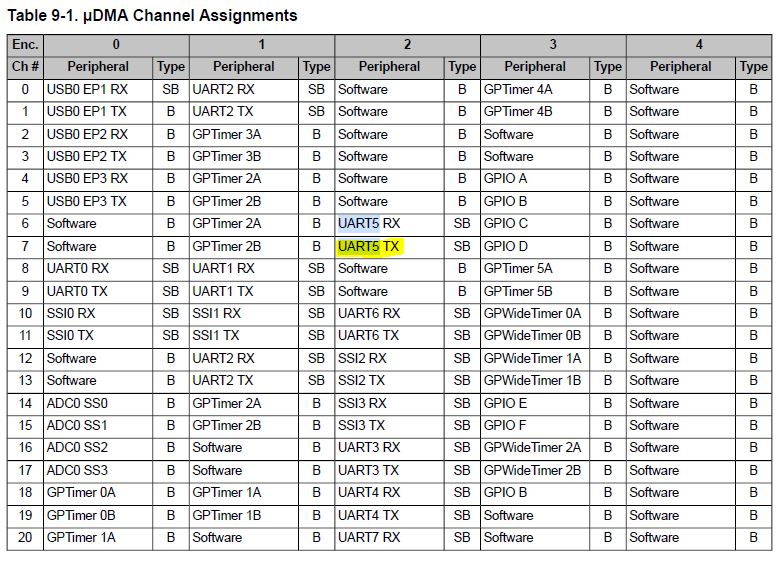
// Select peripheral for channel 7
UDMA_CHMAP0_R = 0x20000000; // UART5_TX
UDMA_USEBURSTSET_R= BIT7; //µDMA channel [n] responds only to burst requests.
//*************************************************************************

//******************* Modified to trasnfer from buffer to peripheral ******
ucControlTable[CH7] = (uint32_t)source+63; // last address

//2. Program the destination end pointer at offset 0x074 to the address of the peripheral's transmit
//FIFO register (UART5_DR_R).
ucControlTable[CH7+1] = (uint32_t)UART5_DR_R; // last address

ucControlTable[CH7+2] = 0xC0008001+((count-1)<<4); //DMA Channel Control (DMACHCTL)

//Start transfer
UDMA_ENASET_R = BIT7; // µDMA Channel 7 is enabled.

UART5_DMACTL_R =UART_DMACTL_TXDMAE ;// µDMA for the transmit FIFO is enabled

UART5_DMACTL_R |=(1u<<1); // Transmit DMA Enable
//*************************************************************************


//**************************UART registers related to DMA ******************

UART5_LCRH_R= 0x00000070;// SPS:WLEN[2]:FEN

UART5_CC_R=0x0 ;//System clock (based on clock source and divisor factor)=80Mhz

UART5_CTL_R|=(1u<< 8)|(1u <<0)|(1u<<4); //UARTEN=1, FIFO enable
UART5_ICR_R =0xFFFFFFFF; // clear all int

UART5_IFLS_R |=0x00000003; // 4bytes or less generate event

//*************************************************************************

  • HI,


    Oman Oman said:
    because
    when I write characters to the UART's buffer, it sends them to Putty terminal.

      What do you mean the characters are sent to the PUtty terminal? You are using UART5. Are you using the LaunchPad or you have your own custom board? The UART5 on the LaunchPad is not connected to Virtual terminal; only UART0 is. How can you send to Putty terminal on UART5 if you are using the LanchPad unless you have a FTDI chip or USB-to-UART adapter connecting between the UART5 and the terminal window. 

      In order for the uDMA to start transfers, it needs to receive a uDMA request from the UART. For the UART to generate the uDMA request, you need to have at least one empty space in he TX FIFO. Do you meet this condition? 

      BTW, refer to item #4 in our support FAQ. https://e2e.ti.com/support/microcontrollers/other/f/908/t/695568. Creating your software using DRM method is very prone to errors. We do not support DRM style of coding. If possible, use the TivaWare. If you must use DRM, you can look at the TivaWare source code on how it configures the uDMA and UART. The TivaWare also has uDMA example with UART that you can find in <TivaWare_Installation>/examples/boards/ek-tm4c123gxl/udma_demo. 

    14.3.11 DMA Operation
    The UART provides an interface to the μDMA controller with separate channels for transmit and
    receive. The DMA operation of the UART is enabled through the UART DMA Control
    (UARTDMACTL) register. When DMA operation is enabled, the UART asserts a DMA request on
    the receive or transmit channel when the associated FIFO can transfer data. For the receive channel,
    a single transfer request is asserted whenever any data is in the receive FIFO. A burst transfer
    request is asserted whenever the amount of data in the receive FIFO is at or above the FIFO trigger
    level configured in the UARTIFLS register. For the transmit channel, a single transfer request is
    asserted whenever there is at least one empty location in the transmit FIFO. The burst request is
    asserted whenever the transmit FIFO contains fewer characters than the FIFO trigger level. The
    single and burst DMA transfer requests are handled automatically by the μDMA controller depending
    on how the DMA channel is configured.


    To enable DMA operation for the receive channel, set the RXDMAE bit of the DMA Control
    (UARTDMACTL) register. To enable DMA operation for the transmit channel, set the TXDMAE bit
    of the UARTDMACTL register. The UART can also be configured to stop using DMA for the receive
    channel if a receive error occurs. If the DMAERR bit of the UARTDMACR register is set and a receive
    error occurs, the DMA receive requests are automatically disabled. This error condition can be
    cleared by clearing the appropriate UART error interrupt.


    If the μDMA is enabled, then the controller triggers an interrupt when the TX FIFO or RX FIFO has
    reached a trigger point as programmed in the UARTIFLS register. The interrupt occurs on the UART
    interrupt vector. Therefore, if interrupts are used for UART operation and DMA is enabled, the UART
    interrupt handler must be designed to handle the μDMA completion interrupt.

  • Hi Charles,

    "You are using UART5. Are you using the LaunchPad or you have your own custom board?"  (correct)

    "The UART5 on the LaunchPad is not connected to Virtual terminal; only UART0 is. How can you send to Putty terminal on UART5 if you are using the LanchPad unless you have a FTDI chip or USB-to-UART adapter connecting between the UART5 and the terminal window:

    (correct. In addition, UART1 and UART5 (PE4,PE5) are working fine with Putty.)

    "For the UART to generate the uDMA request, you need to have at least one empty space in he TX FIFO. Do you meet this condition? "

    (correct. TXFIFO is empty)

    All the sections you mentioned to read  I went over them many times. You can see my initialization and the comments.

    The board I configure to run on 80 Mhz.

    Do you think some of the UARTs are not connected to DMA?

    Thanks 

  • What does the DMAWAITSTAT register show? This register indicates if the uDMA is waiting for a request from the peripheral. As I mentioned in my last reply we do not support DRM. I will suggest you try the TivaWare example first. After the uDMA and UART are initialized, look at the register settings in these two modules in the CCS (or your choice of the debugger) register browser window. Next, bring up your own DRM program and also look at the register settings in those two modules. You can then compare the register settings between the TivaWare example and yours and find out if there is any mis-configuration. 

    You can also modify the TivaWare uDMA example to transfer to UART5 instead of UART1. It should work for all UARTs that are listed in the datasheet including UART5.

  • UDMA_WAITSTAT_R. The bit that's corresponding to the channel is set. The corresponding channel is waiting on a request.

    Either the UART doesn't raise request or the uDMA doesn't response. 

  • Then you need to find out why the UART side is not sending the request. As I said, use the TivaWare to get the register configuration and compare with yours. 

  • FYI,  when I activate a clock to a peripheral, I wait for the bit to be set. I follow the protocol of setting.

  • Hello Charles , 

    The attached file is introduced by a tech-support. I commented unwanted statements to make

    the program uDMA sends buffer contents which contains 8 A's -> UART1--->FDTI232---> PuTTY.

    I'm suppose to get 8 A's, but I get one n.

    UART without uDMA sends strings to PuTTY as expected.

    Why uDMA-->UART-->FDTI232---> PuTTY is not working.

    Best regards

    #include <stdint.h>
    #include <stdbool.h>
    #include "inc/hw_ints.h"
    #include "inc/hw_memmap.h"
    #include "inc/hw_types.h"
    #include "inc/hw_uart.h"
    #include "driverlib/fpu.h"
    #include "driverlib/gpio.h"
    #include "driverlib/interrupt.h"
    #include "driverlib/pin_map.h"
    #include "driverlib/rom.h"
    #include "driverlib/sysctl.h"
    #include "driverlib/systick.h"
    #include "driverlib/uart.h"
    #include "driverlib/udma.h"
    #include "utils/cpu_usage.h"
    #include "utils/uartstdio.h"
    #include "utils/ustdlib.h"
    
    //*****************************************************************************
    //
    //! \addtogroup example_list
    //! <h1>uDMA (udma_demo)</h1>
    //!
    //! This example application demonstrates the use of the uDMA controller to
    //! transfer data between memory buffers, and to transfer data to and from a
    //! UART.  The test runs for 10 seconds before exiting.
    //!
    //! UART0, connected to the FTDI virtual COM port and running at 115,200,
    //! 8-N-1, is used to display messages from this application.
    //
    //*****************************************************************************
    
    //*****************************************************************************
    //
    // The number of SysTick ticks per second used for the SysTick interrupt.
    //
    //*****************************************************************************
    #define SYSTICKS_PER_SECOND     100
    
    //*****************************************************************************
    //
    // The size of the memory transfer source and destination buffers (in words).
    //
    //*****************************************************************************
    #define MEM_BUFFER_SIZE         1024
    
    //*****************************************************************************
    //
    // The size of the UART transmit and receive buffers.  They do not need to be
    // the same size.
    //
    //*****************************************************************************
    #define UART_TXBUF_SIZE         8 //256
    #define UART_RXBUF_SIZE         256
    
    //*****************************************************************************
    //
    // The source and destination buffers used for memory transfers.
    //
    //*****************************************************************************
    static uint32_t g_ui32SrcBuf[MEM_BUFFER_SIZE];
    static uint32_t g_ui32DstBuf[MEM_BUFFER_SIZE];
    
    //*****************************************************************************
    //
    // The transmit and receive buffers used for the UART transfers.  There is one
    // transmit buffer and a pair of recieve ping-pong buffers.
    //
    //*****************************************************************************
    static uint8_t g_ui8TxBuf[UART_TXBUF_SIZE];
    static uint8_t g_ui8RxBufA[UART_RXBUF_SIZE];
    static uint8_t g_ui8RxBufB[UART_RXBUF_SIZE];
    
    //*****************************************************************************
    //
    // The count of uDMA errors.  This value is incremented by the uDMA error
    // handler.
    //
    //*****************************************************************************
    static uint32_t g_ui32uDMAErrCount = 0;
    
    //*****************************************************************************
    //
    // The count of times the uDMA interrupt occurred but the uDMA transfer was not
    // complete.  This should remain 0.
    //
    //*****************************************************************************
    static uint32_t g_ui32BadISR = 0;
    
    //*****************************************************************************
    //
    // The count of UART buffers filled, one for each ping-pong buffer.
    //
    //*****************************************************************************
    static uint32_t g_ui32RxBufACount = 0;
    static uint32_t g_ui32RxBufBCount = 0;
    
    //*****************************************************************************
    //
    // The count of memory uDMA transfer blocks.  This value is incremented by the
    // uDMA interrupt handler whenever a memory block transfer is completed.
    //
    //*****************************************************************************
    static uint32_t g_ui32MemXferCount = 0;
    
    //*****************************************************************************
    //
    // The CPU usage in percent, in 16.16 fixed point format.
    //
    //*****************************************************************************
    static uint32_t g_ui32CPUUsage;
    
    //*****************************************************************************
    //
    // The number of seconds elapsed since the start of the program.  This value is
    // maintained by the SysTick interrupt handler.
    //
    //*****************************************************************************
    static uint32_t g_ui32Seconds = 0;
    
    //*****************************************************************************
    //
    // The control table used by the uDMA controller.  This table must be aligned
    // to a 1024 byte boundary.
    //
    //*****************************************************************************
    #if defined(ewarm)
    #pragma data_alignment=1024
    uint8_t ui8ControlTable[1024];
    #elif defined(ccs)
    #pragma DATA_ALIGN(ui8ControlTable, 1024)
    uint8_t ui8ControlTable[1024];
    #else
    uint8_t ui8ControlTable[1024] __attribute__ ((aligned(1024)));
    #endif
    
    //*****************************************************************************
    //
    // The error routine that is called if the driver library encounters an error.
    //
    //*****************************************************************************
    #ifdef DEBUG
    void
    __error__(char *pcFilename, uint32_t ui32Line)
    {
        while(1)
        {
            //
            // Hang on runtime error.
            //
        }
    }
    #endif
    
    //*****************************************************************************
    //
    // The interrupt handler for the SysTick timer.  This handler will increment a
    // seconds counter whenever the appropriate number of ticks has occurred.  It
    // will also call the CPU usage tick function to find the CPU usage percent.
    //
    //*****************************************************************************
    void SysTickHandler(void)
    {
        static uint32_t ui32TickCount = 0;
    
        //
        // Increment the tick counter.
        //
        ui32TickCount++;
    
        //
        // If the number of ticks per second has occurred, then increment the
        // seconds counter.
        //
        if(!(ui32TickCount % SYSTICKS_PER_SECOND))
        {
            g_ui32Seconds++;
        }
    
        //
        // Call the CPU usage tick function.  This function will compute the amount
        // of cycles used by the CPU since the last call and return the result in
        // percent in fixed point 16.16 format.
        //
        g_ui32CPUUsage = CPUUsageTick();
    }
    
    //*****************************************************************************
    //
    // The interrupt handler for uDMA errors.  This interrupt will occur if the
    // uDMA encounters a bus error while trying to perform a transfer.  This
    // handler just increments a counter if an error occurs.
    //
    //*****************************************************************************
    void
    uDMAErrorHandler(void)
    {
        uint32_t ui32Status;
    
        //
        // Check for uDMA error bit
        //
        ui32Status = ROM_uDMAErrorStatusGet();
    
        //
        // If there is a uDMA error, then clear the error and increment
        // the error counter.
        //
        if(ui32Status)
        {
            ROM_uDMAErrorStatusClear();
            g_ui32uDMAErrCount++;
        }
    }
    
    //*****************************************************************************
    //
    // The interrupt handler for uDMA interrupts from the memory channel.  This
    // interrupt will increment a counter, and then restart another memory
    // transfer.
    //
    //*****************************************************************************
    void
    uDMAIntHandler(void)
    {
        uint32_t ui32Mode;
    
        //
        // Check for the primary control structure to indicate complete.
        //
        ui32Mode = ROM_uDMAChannelModeGet(UDMA_CHANNEL_UART1TX);
        if(ui32Mode == UDMA_MODE_STOP)
        {
            //
            // Increment the count of completed transfers.
            //
            g_ui32MemXferCount++;
    
            //
            // Configure it for another transfer.
            //
            ROM_uDMAChannelTransferSet(UDMA_CHANNEL_UART1TX, UDMA_MODE_AUTO,
                                         g_ui32SrcBuf, g_ui32DstBuf,
                                         MEM_BUFFER_SIZE);
    
            //
            // Initiate another transfer.
            //
            ROM_uDMAChannelEnable(UDMA_CHANNEL_UART1TX);
            ROM_uDMAChannelRequest(UDMA_CHANNEL_UART1TX);
        }
    
        //
        // If the channel is not stopped, then something is wrong.
        //
        else
        {
            g_ui32BadISR++;
        }
    }
    
    //*****************************************************************************
    //
    // The interrupt handler for UART1.  This interrupt will occur when a DMA
    // transfer is complete using the UART1 uDMA channel.  It will also be
    // triggered if the peripheral signals an error.  This interrupt handler will
    // switch between receive ping-pong buffers A and B.  It will also restart a TX
    // uDMA transfer if the prior transfer is complete.  This will keep the UART
    // running continuously (looping TX data back to RX).
    //
    //*****************************************************************************
    void UART1IntHandler(void)
    {
        uint32_t ui32Status;
        uint32_t ui32Mode;
    
        //
        // Read the interrupt status of the UART.
    
        //
        ui32Status = ROM_UARTIntStatus(UART1_BASE, 1);
    
        //
        // Clear any pending status, even though there should be none since no UART
        // interrupts were enabled.  If UART error interrupts were enabled, then
        // those interrupts could occur here and should be handled.  Since uDMA is
        // used for both the RX and TX, then neither of those interrupts should be
        // enabled.
        //
        ROM_UARTIntClear(UART1_BASE, ui32Status);
    
        //
        // Check the DMA control table to see if the ping-pong "A" transfer is
        // complete.  The "A" transfer uses receive buffer "A", and the primary
        // control structure.
        //
    #if 0
        ui32Mode = ROM_uDMAChannelModeGet(UDMA_CHANNEL_UART1RX | UDMA_PRI_SELECT);
    
        //
        // If the primary control structure indicates stop, that means the "A"
        // receive buffer is done.  The uDMA controller should still be receiving
        // data into the "B" buffer.
        //
        if(ui32Mode == UDMA_MODE_STOP)
        {
            //
            // Increment a counter to indicate data was received into buffer A.  In
            // a real application this would be used to signal the main thread that
            // data was received so the main thread can process the data.
            //
            g_ui32RxBufACount++;
    
            //
            // Set up the next transfer for the "A" buffer, using the primary
            // control structure.  When the ongoing receive into the "B" buffer is
            // done, the uDMA controller will switch back to this one.  This
            // example re-uses buffer A, but a more sophisticated application could
            // use a rotating set of buffers to increase the amount of time that
            // the main thread has to process the data in the buffer before it is
            // reused.
            //
            ROM_uDMAChannelTransferSet(UDMA_CHANNEL_UART1RX | UDMA_PRI_SELECT,
                                       UDMA_MODE_PINGPONG,
                                       (void *)(UART1_BASE + UART_O_DR),
                                       g_ui8RxBufA, sizeof(g_ui8RxBufA));
        }
    
        //
        // Check the DMA control table to see if the ping-pong "B" transfer is
        // complete.  The "B" transfer uses receive buffer "B", and the alternate
        // control structure.
        //
        ui32Mode = ROM_uDMAChannelModeGet(UDMA_CHANNEL_UART1RX | UDMA_ALT_SELECT);
    
        //
        // If the alternate control structure indicates stop, that means the "B"
        // receive buffer is done.  The uDMA controller should still be receiving
        // data into the "A" buffer.
        //
        if(ui32Mode == UDMA_MODE_STOP)
        {
            //
            // Increment a counter to indicate data was received into buffer A.  In
            // a real application this would be used to signal the main thread that
            // data was received so the main thread can process the data.
            //
            g_ui32RxBufBCount++;
    
            //
            // Set up the next transfer for the "B" buffer, using the alternate
            // control structure.  When the ongoing receive into the "A" buffer is
            // done, the uDMA controller will switch back to this one.  This
            // example re-uses buffer B, but a more sophisticated application could
            // use a rotating set of buffers to increase the amount of time that
            // the main thread has to process the data in the buffer before it is
            // reused.
            //
            ROM_uDMAChannelTransferSet(UDMA_CHANNEL_UART1RX | UDMA_ALT_SELECT,
                                       UDMA_MODE_PINGPONG,
                                       (void *)(UART1_BASE + UART_O_DR),
                                       g_ui8RxBufB, sizeof(g_ui8RxBufB));
        }
    #endif
        //
        // If the UART1 DMA TX channel is disabled, that means the TX DMA transfer
        // is done.
        //
        if(!ROM_uDMAChannelIsEnabled(UDMA_CHANNEL_UART1TX))
        {
            //
            // Start another DMA transfer to UART1 TX.
            //
            ROM_uDMAChannelTransferSet(UDMA_CHANNEL_UART1TX | UDMA_PRI_SELECT,
                                       UDMA_MODE_BASIC, g_ui8TxBuf,
                                       (void *)(UART1_BASE + UART_O_DR),
                                       sizeof(g_ui8TxBuf));
    
            //
            // The uDMA TX channel must be re-enabled.
            //
            ROM_uDMAChannelEnable(UDMA_CHANNEL_UART1TX);
        }
    }
    
    //*****************************************************************************
    //
    // Initializes the UART1 peripheral and sets up the TX and RX uDMA channels.
    // The UART is configured for loopback mode so that any data sent on TX will be
    // received on RX.  The uDMA channels are configured so that the TX channel
    // will copy data from a buffer to the UART TX output.  And the uDMA RX channel
    // will receive any incoming data into a pair of buffers in ping-pong mode.
    //
    //*****************************************************************************
    void InitUART1Transfer(void)
    {
        unsigned int uIdx;
    
        //
        // Fill the TX buffer with a simple data pattern.
        //
        for(uIdx = 0; uIdx < UART_TXBUF_SIZE; uIdx++)
        {
            g_ui8TxBuf[uIdx] = 'A';//uIdx;
        }
    
        //
        // Enable the UART peripheral, and configure it to operate even if the CPU
        // is in sleep.
        //
        ROM_SysCtlPeripheralEnable(SYSCTL_PERIPH_UART1);
        ROM_SysCtlPeripheralSleepEnable(SYSCTL_PERIPH_UART1);
    
        //
        // Configure the UART communication parameters.
        //
        ROM_UARTConfigSetExpClk(UART1_BASE, ROM_SysCtlClockGet(), 9600,
                                UART_CONFIG_WLEN_8 | UART_CONFIG_STOP_ONE |
                                UART_CONFIG_PAR_NONE);
    
        //
        // Set both the TX and RX trigger thresholds to 4.  This will be used by
        // the uDMA controller to signal when more data should be transferred.  The
        // uDMA TX and RX channels will be configured so that it can transfer 4
        // bytes in a burst when the UART is ready to transfer more data.
        //
        ROM_UARTFIFOLevelSet(UART1_BASE, UART_FIFO_TX4_8, UART_FIFO_RX4_8);
    
        //
        // Enable the UART for operation, and enable the uDMA interface for both TX
        // and RX channels.
        //
        ROM_UARTEnable(UART1_BASE);
        //ROM_UARTDMAEnable(UART1_BASE, UART_DMA_RX | UART_DMA_TX);
        ROM_UARTDMAEnable(UART1_BASE, UART_DMA_TX);
    
        //
        // This register write will set the UART to operate in loopback mode.  Any
        // data sent on the TX output will be received on the RX input.
        // UART_O_CTL is (UARTCTL) reg
        //HWREG(UART1_BASE + UART_O_CTL) |= UART_CTL_LBE;
    
        //
        // Enable the UART peripheral interrupts.  Note that no UART interrupts
        // were enabled, but the uDMA controller will cause an interrupt on the
        // UART interrupt signal when a uDMA transfer is complete.
        //
        ROM_IntEnable(INT_UART1);
    
        //
        // Put the attributes in a known state for the uDMA UART1RX channel.  These
        // should already be disabled by default.
        //
        //ROM_uDMAChannelAttributeDisable(UDMA_CHANNEL_UART1RX,
                                        //UDMA_ATTR_ALTSELECT | UDMA_ATTR_USEBURST |
                                        //UDMA_ATTR_HIGH_PRIORITY |
                                        //UDMA_ATTR_REQMASK);
    #if 0
        //
        // Configure the control parameters for the primary control structure for
        // the UART RX channel.  The primary control structure is used for the "A"
        // part of the ping-pong receive.  The transfer data size is 8 bits, the
        // source address does not increment since it will be reading from a
        // register.  The destination address increment is byte 8-bit bytes.  The
        // arbitration size is set to 4 to match the RX FIFO trigger threshold.
        // The uDMA controller will use a 4 byte burst transfer if possible.  This
        // will be somewhat more efficient that single byte transfers.
        //
        //ROM_uDMAChannelControlSet(UDMA_CHANNEL_UART1RX | UDMA_PRI_SELECT,
                                 // UDMA_SIZE_8 | UDMA_SRC_INC_NONE | UDMA_DST_INC_8 |
                                 // UDMA_ARB_4);
    
        //
        // Configure the control parameters for the alternate control structure for
        // the UART RX channel.  The alternate contol structure is used for the "B"
        // part of the ping-pong receive.  The configuration is identical to the
        // primary/A control structure.
        //
        ROM_uDMAChannelControlSet(UDMA_CHANNEL_UART1RX | UDMA_ALT_SELECT,
                                  UDMA_SIZE_8 | UDMA_SRC_INC_NONE | UDMA_DST_INC_8 |
                                  UDMA_ARB_4);
    
        //
        // Set up the transfer parameters for the UART RX primary control
        // structure.  The mode is set to ping-pong, the transfer source is the
        // UART data register, and the destination is the receive "A" buffer.  The
        // transfer size is set to match the size of the buffer.
        //
        ROM_uDMAChannelTransferSet(UDMA_CHANNEL_UART1RX | UDMA_PRI_SELECT,
                                   UDMA_MODE_PINGPONG,
                                   (void *)(UART1_BASE + UART_O_DR),
                                   g_ui8RxBufA, sizeof(g_ui8RxBufA));
    
        //
        // Set up the transfer parameters for the UART RX alternate control
        // structure.  The mode is set to ping-pong, the transfer source is the
        // UART data register, and the destination is the receive "B" buffer.  The
        // transfer size is set to match the size of the buffer.
        //
        ROM_uDMAChannelTransferSet(UDMA_CHANNEL_UART1RX | UDMA_ALT_SELECT,
                                   UDMA_MODE_PINGPONG,
                                   (void *)(UART1_BASE + UART_O_DR),
                                   g_ui8RxBufB, sizeof(g_ui8RxBufB));
    #endif
        //
        // Put the attributes in a known state for the uDMA UART1TX channel.  These
        // should already be disabled by default.
        //
    
    
        ROM_uDMAChannelAttributeDisable(UDMA_CHANNEL_UART1TX,
                                        UDMA_ATTR_ALTSELECT |
                                        UDMA_ATTR_HIGH_PRIORITY |
                                        UDMA_ATTR_REQMASK);
    
        //
        // Set the USEBURST attribute for the uDMA UART TX channel.  This will
        // force the controller to always use a burst when transferring data from
        // the TX buffer to the UART.  This is somewhat more effecient bus usage
        // than the default which allows single or burst transfers.
        //
        ROM_uDMAChannelAttributeEnable(UDMA_CHANNEL_UART1TX, UDMA_ATTR_USEBURST);
    
        //
        // Configure the control parameters for the UART TX.  The uDMA UART TX
        // channel is used to transfer a block of data from a buffer to the UART.
        // The data size is 8 bits.  The source address increment is 8-bit bytes
        // since the data is coming from a buffer.  The destination increment is
        // none since the data is to be written to the UART data register.  The
        // arbitration size is set to 4, which matches the UART TX FIFO trigger
        // threshold.
        //
        ROM_uDMAChannelControlSet(UDMA_CHANNEL_UART1TX | UDMA_PRI_SELECT,
                                  UDMA_SIZE_8 | UDMA_SRC_INC_8 | UDMA_DST_INC_NONE |
                                  UDMA_ARB_4);
    
        //
        // Set up the transfer parameters for the uDMA UART TX channel.  This will
        // configure the transfer source and destination and the transfer size.
        // Basic mode is used because the peripheral is making the uDMA transfer
        // request.  The source is the TX buffer and the destination is the UART
        // data register.
        //UART_O_DR is (UARTDR) register at offset 0x000
        ROM_uDMAChannelTransferSet(UDMA_CHANNEL_UART1TX | UDMA_PRI_SELECT,
                                   UDMA_MODE_BASIC, g_ui8TxBuf,
                                   (void *)(UART1_BASE + UART_O_DR),
                                   sizeof(g_ui8TxBuf));
    
        //
        // Now both the uDMA UART TX and RX channels are primed to start a
        // transfer.  As soon as the channels are enabled, the peripheral will
        // issue a transfer request and the data transfers will begin.
        //
        //ROM_uDMAChannelEnable(UDMA_CHANNEL_UART1RX);
        ROM_uDMAChannelEnable(UDMA_CHANNEL_UART1TX);
    
    }
    
    //*****************************************************************************
    //
    // Initializes the uDMA software channel to perform a memory to memory uDMA
    // transfer.
    //
    //*****************************************************************************
    void
    InitSWTransfer(void)
    {
        unsigned int uIdx;
    
        //
        // Fill the source memory buffer with a simple incrementing pattern.
        //
        for(uIdx = 0; uIdx < MEM_BUFFER_SIZE; uIdx++)
        {
            g_ui32SrcBuf[uIdx] = uIdx;
        }
    
        //
        // Enable interrupts from the uDMA software channel.
        //
        ROM_IntEnable(INT_UDMA);
    
        //
        // Put the attributes in a known state for the uDMA software channel.
        // These should already be disabled by default.
        //
        ROM_uDMAChannelAttributeDisable(UDMA_CHANNEL_SW,
                                        UDMA_ATTR_USEBURST | UDMA_ATTR_ALTSELECT |
                                        (UDMA_ATTR_HIGH_PRIORITY |
                                        UDMA_ATTR_REQMASK));
    
        //
        // Configure the control parameters for the SW channel.  The SW channel
        // will be used to transfer between two memory buffers, 32 bits at a time.
        // Therefore the data size is 32 bits, and the address increment is 32 bits
        // for both source and destination.  The arbitration size will be set to 8,
        // which causes the uDMA controller to rearbitrate after 8 items are
        // transferred.  This keeps this channel from hogging the uDMA controller
        // once the transfer is started, and allows other channels cycles if they
        // are higher priority.
        //
        ROM_uDMAChannelControlSet(UDMA_CHANNEL_SW | UDMA_PRI_SELECT,
                                  UDMA_SIZE_32 | UDMA_SRC_INC_32 | UDMA_DST_INC_32 |
                                  UDMA_ARB_8);
    
        //
        // Set up the transfer parameters for the software channel.  This will
        // configure the transfer buffers and the transfer size.  Auto mode must be
        // used for software transfers.
        //
        ROM_uDMAChannelTransferSet(UDMA_CHANNEL_SW | UDMA_PRI_SELECT,
                                   UDMA_MODE_AUTO, g_ui32SrcBuf, g_ui32DstBuf,
                                   MEM_BUFFER_SIZE);
    
        //
        // Now the software channel is primed to start a transfer.  The channel
        // must be enabled.  For software based transfers, a request must be
        // issued.  After this, the uDMA memory transfer begins.
        //
        ROM_uDMAChannelEnable(UDMA_CHANNEL_SW);
        ROM_uDMAChannelRequest(UDMA_CHANNEL_SW);
    }
    
    //*****************************************************************************
    //
    // Configure the UART and its pins.  This must be called before UARTprintf().
    //
    //*****************************************************************************
    void ConfigureUART(void)
    {
        //
        // Enable the GPIO Peripheral used by the UART.
        //
        ROM_SysCtlPeripheralEnable(SYSCTL_PERIPH_GPIOB);
    
        //
        // Enable UART1
        //
        ROM_SysCtlPeripheralEnable(SYSCTL_PERIPH_UART1);
        ROM_SysCtlPeripheralSleepEnable(SYSCTL_PERIPH_UART1);
    
        //
        // Configure GPIO Pins for UART mode.
        //
        ROM_GPIOPinConfigure(GPIO_PB0_U1RX);
        ROM_GPIOPinConfigure(GPIO_PB1_U1TX);
        ROM_GPIOPinTypeUART(GPIO_PORTB_BASE, GPIO_PIN_0 | GPIO_PIN_1);
    
        //
        // Use the internal 16MHz oscillator as the UART clock source.
        //
        UARTClockSourceSet(UART1_BASE, UART_CLOCK_PIOSC);
    
        //
        // Initialize the UART for console I/O.
        //
        //UARTStdioConfig(0, 9600, 16000000);
        UARTStdioConfig(1, 9600, 16000000);
    }
    
    //*****************************************************************************
    //
    // This example demonstrates how to use the uDMA controller to transfer data
    // between memory buffers and to and from a peripheral, in this case a UART.
    // The uDMA controller is configured to repeatedly transfer a block of data
    // from one memory buffer to another.  It is also set up to repeatedly copy a
    // block of data from a buffer to the UART output.  The UART data is looped
    // back so the same data is received, and the uDMA controlled is configured to
    // continuously receive the UART data using ping-pong buffers.
    //
    // The processor is put to sleep when it is not doing anything, and this allows
    // collection of CPU usage data to see how much CPU is being used while the
    // data transfers are ongoing.
    //
    //*****************************************************************************
    int main(void)
    {
        static uint32_t ui32PrevSeconds;
        static uint32_t ui32PrevXferCount;
        static uint32_t ui32PrevUARTCount = 0;
        uint32_t ui32XfersCompleted;
        uint32_t ui32BytesTransferred;
    
        //
        // Enable lazy stacking for interrupt handlers.  This allows floating-point
        // instructions to be used within interrupt handlers, but at the expense of
        // extra stack usage.
        //
        ROM_FPULazyStackingEnable();
    
        //
        // Set the clocking to run from the PLL at 50 MHz.
        //
        ROM_SysCtlClockSet(SYSCTL_SYSDIV_4 | SYSCTL_USE_PLL | SYSCTL_OSC_MAIN |
                           SYSCTL_XTAL_16MHZ);
    
        //
        // Enable peripherals to operate when CPU is in sleep.
        //
        ROM_SysCtlPeripheralClockGating(true);
    
        //
        // Enable the GPIO port that is used for the on-board LED.
        //
        ROM_SysCtlPeripheralEnable(SYSCTL_PERIPH_GPIOF);
    
        //
        // Enable the GPIO pins for the LED (PF2).
        //
        ROM_GPIOPinTypeGPIOOutput(GPIO_PORTF_BASE, GPIO_PIN_2);
    
        //
        // Initialize the UART.
        //
        ConfigureUART();
    #if 0
        UARTprintf("\033[2JuDMA Example\n");
    
        //
        // Show the clock frequency on the display.
        //
        UARTprintf("Tiva C Series @ %u MHz\n\n", ROM_SysCtlClockGet() / 1000000);
    
        //
        // Show statistics headings.
        //
        UARTprintf("CPU    Memory     UART       Remaining\n");
        UARTprintf("Usage  Transfers  Transfers  Time\n");
    #endif
        //
        // Configure SysTick to occur 100 times per second, to use as a time
        // reference.  Enable SysTick to generate interrupts.
        //
        ROM_SysTickPeriodSet(ROM_SysCtlClockGet() / SYSTICKS_PER_SECOND);
    #if 0
        ROM_SysTickIntEnable();
        ROM_SysTickEnable();
    #endif
        //
        // Initialize the CPU usage measurement routine.
        //
        CPUUsageInit(ROM_SysCtlClockGet(), SYSTICKS_PER_SECOND, 2);
    
        //
        // Enable the uDMA controller at the system level.  Enable it to continue
        // to run while the processor is in sleep.
        //
        ROM_SysCtlPeripheralEnable(SYSCTL_PERIPH_UDMA);
        ROM_SysCtlPeripheralSleepEnable(SYSCTL_PERIPH_UDMA);
    
        //
        // Enable the uDMA controller error interrupt.  This interrupt will occur
        // if there is a bus error during a transfer.
        //
        ROM_IntEnable(INT_UDMAERR);
    
        //
        // Enable the uDMA controller.
        //
        ROM_uDMAEnable();
    
        //
        // Point at the control table to use for channel control structures.
        //
        ROM_uDMAControlBaseSet(ui8ControlTable);
    
        //
        // Initialize the uDMA memory to memory transfers.
        //
        //InitSWTransfer(); //  comments
    
        //
        // Initialize the uDMA UART transfers.
        //
        InitUART1Transfer();
    
        //
        // Remember the current SysTick seconds count.
        //
        ui32PrevSeconds = g_ui32Seconds;
    
        //
        // Remember the current count of memory buffer transfers.
        //
        ui32PrevXferCount = g_ui32MemXferCount;
    
        //
        // Loop until the button is pressed.  The processor is put to sleep
        // in this loop so that CPU utilization can be measured.
        //
    #if 0
        while(1)
        {
            //
            // Check to see if one second has elapsed.  If so, the make some
            // updates.
            //
            if(g_ui32Seconds != ui32PrevSeconds)
            {
                //
                // Turn on the LED as a heartbeat
                //
                GPIOPinWrite(GPIO_PORTF_BASE, GPIO_PIN_2, GPIO_PIN_2);
    
                //
                // Print a message to the display showing the CPU usage percent.
                // The fractional part of the percent value is ignored.
                //
                UARTprintf("\r%3d%%   ", g_ui32CPUUsage >> 16);
    
                //
                // Remember the new seconds count.
                //
                ui32PrevSeconds = g_ui32Seconds;
    
                //
                // Calculate how many memory transfers have occurred since the last
                // second.
                //
                ui32XfersCompleted = g_ui32MemXferCount - ui32PrevXferCount;
    
                //
                // Remember the new transfer count.
                //
                ui32PrevXferCount = g_ui32MemXferCount;
    
                //
                // Compute how many bytes were transferred in the memory transfer
                // since the last second.
                //
                ui32BytesTransferred = ui32XfersCompleted * MEM_BUFFER_SIZE * 4;
    
                //
                // Print a message showing the memory transfer rate.
                //
                if(ui32BytesTransferred >= 100000000)
                {
                    UARTprintf("%3d MB/s   ", ui32BytesTransferred / 1000000);
                }
                else if(ui32BytesTransferred >= 10000000)
                {
                    UARTprintf("%2d.%01d MB/s  ", ui32BytesTransferred / 1000000,
                               (ui32BytesTransferred % 1000000) / 100000);
                }
                else if(ui32BytesTransferred >= 1000000)
                {
                    UARTprintf("%1d.%02d MB/s  ", ui32BytesTransferred / 1000000,
                               (ui32BytesTransferred % 1000000) / 10000);
                }
                else if(ui32BytesTransferred >= 100000)
                {
                    UARTprintf("%3d KB/s   ", ui32BytesTransferred / 1000);
                }
                else if(ui32BytesTransferred >= 10000)
                {
                    UARTprintf("%2d.%01d KB/s  ", ui32BytesTransferred / 1000,
                               (ui32BytesTransferred % 1000) / 100);
                }
                else if(ui32BytesTransferred >= 1000)
                {
                    UARTprintf("%1d.%02d KB/s  ", ui32BytesTransferred / 1000,
                               (ui32BytesTransferred % 1000) / 10);
                }
                else if(ui32BytesTransferred >= 100)
                {
                    UARTprintf("%3d B/s    ", ui32BytesTransferred);
                }
                else if(ui32BytesTransferred >= 10)
                {
                    UARTprintf("%2d B/s     ", ui32BytesTransferred);
                }
                else
                {
                    UARTprintf("%1d B/s      ", ui32BytesTransferred);
                }
    
                //
                // Calculate how many UART transfers have occurred since the last
                // second.
                //
                ui32XfersCompleted = (g_ui32RxBufACount + g_ui32RxBufBCount -
                                      ui32PrevUARTCount);
    
                //
                // Remember the new UART transfer count.
                //
                ui32PrevUARTCount = g_ui32RxBufACount + g_ui32RxBufBCount;
    
                //
                // Compute how many bytes were transferred by the UART.  The number
                // of bytes received is multiplied by 2 so that the TX bytes
                // transferred are also accounted for.
                //
                ui32BytesTransferred = ui32XfersCompleted * UART_RXBUF_SIZE * 2;
    
                //
                // Print a message showing the UART transfer rate.
                //
                if(ui32BytesTransferred >= 1000000)
                {
                    UARTprintf("%1d.%02d MB/s  ", ui32BytesTransferred / 1000000,
                               (ui32BytesTransferred % 1000000) / 10000);
                }
                else if(ui32BytesTransferred >= 100000)
                {
                    UARTprintf("%3d KB/s   ", ui32BytesTransferred / 1000);
                }
                else if(ui32BytesTransferred >= 10000)
                {
                    UARTprintf("%2d.%01d KB/s  ", ui32BytesTransferred / 1000,
                               (ui32BytesTransferred % 1000) / 100);
                }
                else if(ui32BytesTransferred >= 1000)
                {
                    UARTprintf("%1d.%02d KB/s  ", ui32BytesTransferred / 1000,
                               (ui32BytesTransferred % 1000) / 10);
                }
                else if(ui32BytesTransferred >= 100)
                {
                    UARTprintf("%3d B/s    ", ui32BytesTransferred);
                }
                else if(ui32BytesTransferred >= 10)
                {
                    UARTprintf("%2d B/s     ", ui32BytesTransferred);
                }
                else
                {
                    UARTprintf("%1d B/s      ", ui32BytesTransferred);
                }
    
                //
                // Print a spinning line to make it more apparent that there is
                // something happening.
                //
                UARTprintf("%2ds", 10 - ui32PrevSeconds);
    
                //
                // Turn off the LED.
                //
                GPIOPinWrite(GPIO_PORTF_BASE, GPIO_PIN_2, 0);
            }
    
            //
            // Put the processor to sleep if there is nothing to do.  This allows
            // the CPU usage routine to measure the number of free CPU cycles.
            // If the processor is sleeping a lot, it can be hard to connect to
            // the target with the debugger.
            //
            ROM_SysCtlSleep();
    
            //
            // See if we have run int32_t enough and exit the loop if so.
            //
            if(g_ui32Seconds >= 10)
            {
                break;
            }
        }
    #endif
        //
        // Indicate on the display that the example is stopped.
        //
        //UARTprintf("\nStopped\n");
        //UARTprintf("QR");
    
        // Loop forever with the CPU not sleeping, so the debugger can connect.
        //
        while(1)
        {
            //
            // Turn on the GREEN LED.
            //
            GPIOPinWrite(GPIO_PORTF_BASE, GPIO_PIN_2, GPIO_PIN_2);
    
            //
            // Delay for a bit.
            //
            SysCtlDelay(SysCtlClockGet() / 20 / 3);
    
            //
            // Turn off the GREEN LED.
            //
            GPIOPinWrite(GPIO_PORTF_BASE, GPIO_PIN_2, 0);
    
            //
            // Delay for a bit.
            //
            SysCtlDelay(SysCtlClockGet() / 20 / 3);
    
        }
    }
    

  • I see you are using SW request for the UART. You cannot do that. The SW request is for memory to memory transfer. The UART needs to generate DMA request on its own. Please use the example as is. You can remove the code for the UART RX channel if you are not using it but keep how the TX is setup in the example. 

  • Hi Charles,

    I'm not using SW request. The call for SW request is commented in the code.

    B.regards

  • This is what you wrote.

    //
    // Initiate another transfer.
    //
    ROM_uDMAChannelEnable(UDMA_CHANNEL_UART1TX);
    ROM_uDMAChannelRequest(UDMA_CHANNEL_UART1TX);

  • Charles,

    What is wrong with that?

  • I see in your code you change the ConfigureUART() for UART1 and in InitUART1Transfer() you also configure UART1. Can you make the udma_demo example working as is? If you can get the udma_demo working then you can try to remove just a small port of the code at a time (the code that you don't need for your application) to see what stops it from working. Don't just remove the code that you don't need entirely at once. It will be much harder to debug. 

  • Hi Charles,

    The demo program, I exchange the duty of UART1 and UART0 and the program worked as it's written for.

    My objective is to use on UART such as UART1 to send what it received from uDMA to the terminal.

    I commented any UART RX configuration and removed the loop back( TX-> RX). I kept only what's 

    related to UART TX even in the uDAM side.

    Always, I got what in the screen shot, unrecognized characters. You can see the attached file.

    Even I initialized the buffers in main such:

    for(ui32Mode=0; ui32Mode < 256;ui32Mode++){
    g_ui32SrcBuf[ui32Mode]=(char)'Q';
    g_ui32DstBuf[ui32Mode]=(char)'T';

    g_ui8TxBuf[ui32Mode]=(char)'S';
    g_ui8RxBufA[ui32Mode]=(char)'M';
    g_ui8RxBufB[ui32Mode]=(char)'F';
    }

    It didn't help.prtSc.pdf


  • Hi,

      Do you have the scope or logic analyzer to capture the waveforms?

  • Hi Charles,

    I found what was wrong. It was the change of UART clock source from 16Mhz to 50Mhz.

    Thanks anyway.