This thread has been locked.

If you have a related question, please click the "Ask a related question" button in the top right corner. The newly created question will be automatically linked to this question.

TMDSECATCNCD379D: DSP Dual CPU Usage

Part Number: TMDSECATCNCD379D
Other Parts Discussed in Thread: C2000WARE, CONTROLSUITE,

Hi,

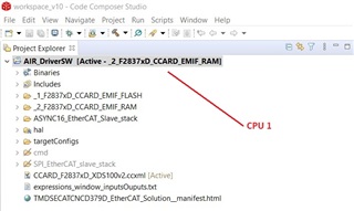
I want to communicate with EtherCAT using dual CPU. I did EtherCAT communication for CPU 1 in DSP. I want to define CPU 2 to DSP and send EtherCAT data from CPU 1 to CPU 2. Also, I will communicate with the driver use the SPI or CAN communication protocol in CPU 2.

I am waiting for your help.

DSC_CPU1

Kind regards.
Thanks.
Sinan.
Good days.
  • Hi Sinan,

    For guidance on communicating between the CPU1 and CPU2 of the F2837xD device, you can take a look at the 'cpu01_to_cpu02_ipcdrivers' software examples in C2000WARE for inter processor communication between the two cores. Directories below.

    C:\ti\c2000\C2000Ware_3_04_00_00\device_support\f2837xd\examples\dual

    Also, I will communicate with the driver use the SPI or CAN communication protocol in CPU 2.

    What will you be communicating with over SPI/CAN exactly? A motor driver you mean and if so is it a TI device?

    Best,

    Kevin

  • Hi, Kevin:

    Thank you very much for your feedback to me. I am grateful to you.

    I've looked at the example of dual CPU usage on device F2837xD. The sample application is very good.

    I will communicate with the an motor driver using the SPI, CAN or EtherCAT communication protocol on CPU 2. My motor driver is not a TI device. My motor is AC/DC servo. There is a different microcontroller (MCU) in the motor driver. I will send the data I received from EtherCAT with CPU 1 from CPU 2 to this MCU.

    Very thanks.
    Sinan.
    Kind regards.

  • Hi Sinan,

    Happy to hear the software example has helped you.

    OK, I better understand your system and topology now. By the way, you can find CAN and SPI software examples for the F2837xD device in C2000WARE as well. They are written for CPU1, but you can make necessary edits to the examples to run on CPU2. Directory location below:

    C:\ti\c2000\C2000Ware_3_04_00_00\device_support\f2837xd\examples\cpu1

    Best,

    Kevin

  • Hi,

    I am trying to make the following application.

    C:\ti\controlSUITE\device_support\F2837xD\v210\F2837xD_examples_Dual\cpu01_to_cpu02_ipcdrivers

    I am successfully doing EtherCAT communication on CPU 1. I am using ET1100 ESC (EtherCAT Slave Controller) for EtherCAT communication. However, on CPU 1, both EtherCAT communication and CPU 2 communication (IPC) do not work together. What do you think could be the reason?

    Also I will send the data I get from EtherCAT with CPU 1 to CPU 2.

    My 'cpu01_to_cpu02_ipcdrivers_cpu01.c' main code:

    /**
    \addtogroup TMDSECATCNCD379D_AIR TMDSECATCNCD379D_AIR
    @{
    */
    /**
    \file TMDSECATCNCD379D_AIR.c
    \brief Implementation
    \version 1.0.0.11
    */
    
    #include "F28x_Project.h"
    #include "F2837xD_Ipc_drivers.h"
    
    #include <stdint.h>
    #include "ecat_def.h"
    
    #include "applInterface.h"
    
    #define _TMDSECATCNCD379_D__AIR_ 1
    #include "TMDSECATCNCD379D_AIR.h"
    #undef _TMDSECATCNCD379_D__AIR_
    
    void PDO_ResetOutputs(void)
    {
    	LEDS0x7000.LED1 = 0x0;
    	LEDS0x7000.LED2 = 0x0;
    	LEDS0x7000.LED3 = 0x0;
    	LEDS0x7000.LED4 = 0x0;
    	LEDS0x7000.LED5 = 0x0;
    	LEDS0x7000.LED6 = 0x0;
    	LEDS0x7000.LED7 = 0x0;
    	LEDS0x7000.LED8 = 0x0;
    
    	DatafromMaster0x7010.DatafromMaster = 0x0;
    	TargetMode0x7012.Mode = 0x0;
    	TargetSpeedPosReq0x7014.SpeedPosReq = 0x0;
    }
    
    void APPL_AckErrorInd(UINT16 stateTrans)
    {
    }
    
    UINT16 APPL_StartMailboxHandler(void)
    {
        return ALSTATUSCODE_NOERROR;
    }
    
    UINT16 APPL_StopMailboxHandler(void)
    {
        return ALSTATUSCODE_NOERROR;
    }
    
    UINT16 APPL_StartInputHandler(UINT16 *pIntMask)
    {
        return ALSTATUSCODE_NOERROR;
    }
    
    UINT16 APPL_StopInputHandler(void)
    {
        return ALSTATUSCODE_NOERROR;
    }
    
    UINT16 APPL_StartOutputHandler(void)
    {
        return ALSTATUSCODE_NOERROR;
    }
    
    UINT16 APPL_StopOutputHandler(void)
    {
        return ALSTATUSCODE_NOERROR;
    }
    
    UINT16 APPL_GenerateMapping(UINT16 *pInputSize,UINT16 *pOutputSize)
    {
        UINT16 result = ALSTATUSCODE_NOERROR;
        UINT16 InputSize = 0;
        UINT16 OutputSize = 0;
    
    #if COE_SUPPORTED
        UINT16 PDOAssignEntryCnt = 0;
        OBJCONST TOBJECT OBJMEM * pPDO = NULL;
        UINT16 PDOSubindex0 = 0;
        UINT32 *pPDOEntry = NULL;
        UINT16 PDOEntryCnt = 0;
       
        /*Scan object 0x1C12 RXPDO assign*/
        for(PDOAssignEntryCnt = 0; PDOAssignEntryCnt < sRxPDOassign.u16SubIndex0; PDOAssignEntryCnt++)
        {
            pPDO = OBJ_GetObjectHandle(sRxPDOassign.aEntries[PDOAssignEntryCnt]);
            if(pPDO != NULL)
            {
                PDOSubindex0 = *((UINT16 *)pPDO->pVarPtr);
                for(PDOEntryCnt = 0; PDOEntryCnt < PDOSubindex0; PDOEntryCnt++)
                {
                    //pPDOEntry = (UINT32 *)((UINT8 *)pPDO->pVarPtr + (OBJ_GetEntryOffset((PDOEntryCnt+1),pPDO)>>3));    //goto PDO entry
                    pPDOEntry = (UINT32 *)((UINT8 *)pPDO->pVarPtr + (OBJ_GetEntryOffset((PDOEntryCnt+1),pPDO)>>4 /*3 - TI C28x Port*/));    //goto PDO entry
        			//need for change  - C28x is 16 bit machine, so each entry is atleast 16 bits (so divide the no. of bits by 16, to get the proper
                    //Pointer increment.
                    // we increment the expected output size depending on the mapped Entry
                    OutputSize += (UINT16) ((*pPDOEntry) & 0xFF);
                }
            }
            else
            {
                /*assigned PDO was not found in object dictionary. return invalid mapping*/
                OutputSize = 0;
                result = ALSTATUSCODE_INVALIDOUTPUTMAPPING;
                break;
            }
        }
    
        OutputSize = (OutputSize + 7) >> 3;
    
        if(result == 0)
        {
            /*Scan Object 0x1C13 TXPDO assign*/
            for(PDOAssignEntryCnt = 0; PDOAssignEntryCnt < sTxPDOassign.u16SubIndex0; PDOAssignEntryCnt++)
            {
                pPDO = OBJ_GetObjectHandle(sTxPDOassign.aEntries[PDOAssignEntryCnt]);
                if(pPDO != NULL)
                {
                    PDOSubindex0 = *((UINT16 *)pPDO->pVarPtr);
                    for(PDOEntryCnt = 0; PDOEntryCnt < PDOSubindex0; PDOEntryCnt++)
                    {
                        //pPDOEntry = (UINT32 *)((UINT8 *)pPDO->pVarPtr + (OBJ_GetEntryOffset((PDOEntryCnt+1),pPDO)>>3));    //goto PDO entry
                        pPDOEntry = (UINT32 *)((UINT8 *)pPDO->pVarPtr + (OBJ_GetEntryOffset((PDOEntryCnt+1),pPDO)>>4 /*3 - TI C28x Port*/));    //goto PDO entry
    					//need for change  - C28x is 16 bit machine, so each entry is atleast 16 bits (so divide the no. of bits by 16, to get the proper
    					//Pointer increment.
                        // we increment the expected output size depending on the mapped Entry
                        InputSize += (UINT16) ((*pPDOEntry) & 0xFF);
                    }
                }
                else
                {
                    /*assigned PDO was not found in object dictionary. return invalid mapping*/
                    InputSize = 0;
                    result = ALSTATUSCODE_INVALIDINPUTMAPPING;
                    break;
                }
            }
        }
        InputSize = (InputSize + 7) >> 3;
    
    #else
    #if _WIN32
       #pragma message ("Warning: Define 'InputSize' and 'OutputSize'.")
    #else
        #warning "Define 'InputSize' and 'OutputSize'."
    #endif
    #endif
    
        *pInputSize = InputSize;
        *pOutputSize = OutputSize;
        return result;
    }
    
    void APPL_InputMapping(UINT16* pData)
    {
    	uint16_t j = 0;
        uint16_t *pTmpData = (uint16_t *)pData;
        uint16_t data;
    
       for (j = 0; j < sTxPDOassign.u16SubIndex0; j++)
       {
          switch (sTxPDOassign.aEntries[j])
          {
          /* TxPDO  */
          case 0x1A00: // 8 bits
        	  data = ((Switches0x6000.Switch8 << 7) | (Switches0x6000.Switch7 << 6) |
    		  (Switches0x6000.Switch6 << 5) | (Switches0x6000.Switch5 << 4) | (Switches0x6000.Switch4 << 3) |
    		  (Switches0x6000.Switch3 << 2) | (Switches0x6000.Switch2 << 1) | Switches0x6000.Switch1);
    
        	  * (volatile uint16_t *)pTmpData = data;
    
             break;
          /* TxPDO 1*/
    	  case 0x1A01:
    	  // 32 bits
                * (volatile uint16_t *)pTmpData |= ((DataToMaster0x6010.DataToMaster) & 0xFF) << 8;
                pTmpData++;
                * (volatile uint16_t *)pTmpData = ((DataToMaster0x6010.DataToMaster) & 0x00FFFF00) >> 8;
                pTmpData++;
                * (volatile uint16_t *)pTmpData = ((DataToMaster0x6010.DataToMaster) & 0xFF000000) >> 24;
    
    	  //16bits
    			* (volatile uint16_t *)pTmpData |= (( TargetModeResponse0x6012.ModeResponse) & 0x00FF) << 8; //8 bits
    			pTmpData++;
    			* (volatile uint16_t *)pTmpData = (( TargetModeResponse0x6012.ModeResponse) & 0xFF00) >> 8; //8 bits
    	  //32bits
    			* (volatile uint16_t *)pTmpData |= ((TargetSpeedPosFeedback0x6014.SpeedPosFbk) & 0xFF) << 8;
    			pTmpData++;
    			* (volatile uint16_t *)pTmpData = ((TargetSpeedPosFeedback0x6014.SpeedPosFbk) & 0x00FFFF00) >> 8;
    			pTmpData++;
    			* (volatile uint16_t *)pTmpData = ((TargetSpeedPosFeedback0x6014.SpeedPosFbk) & 0xFF000000) >> 24;
    			break;
          }
       }	
    	
    void APPL_OutputMapping(UINT16* pData)
    {
    	uint16_t j = 0;
        uint16_t *pTmpData = (uint16_t *)pData;// allow byte processing
        uint16_t data = 0;
        for (j = 0; j < sRxPDOassign.u16SubIndex0; j++)
        {
            switch (sRxPDOassign.aEntries[j])
            {
            /* RxPDO */
            case 0x1600: //byte (8 bits)
            	data = (*(volatile uint16_t *)pTmpData);
            	(LEDS0x7000.LED1) = data & 0x1;
            	data = data >> 1;
            	(LEDS0x7000.LED2) = data  & 0x1;
            	data = data >> 1;
            	(LEDS0x7000.LED3) = data  & 0x1;
            	data = data >> 1;
            	(LEDS0x7000.LED4) = data  & 0x1;
            	data = data >> 1;
            	(LEDS0x7000.LED5) = data  & 0x1;
            	data = data >> 1;
            	(LEDS0x7000.LED6) = data  & 0x1;
            	data = data >> 1;
            	(LEDS0x7000.LED7) = data  & 0x1;
            	data = data >> 1;
            	(LEDS0x7000.LED8) = data  & 0x1;
            	data = data >> 1;
            	break;
    		/* RxPDO 1*/
    		case 0x1601:
    		//32 bits
    			(DatafromMaster0x7010.DatafromMaster) = data & 0xFF;
    			pTmpData++;
    
    			DatafromMaster0x7010.DatafromMaster |= (uint32_t) ((uint32_t)((*(volatile uint16_t *)pTmpData) & 0xFFFF) << 8);
    			pTmpData++; //increment the pointer now that we have read 2 bytes
    			DatafromMaster0x7010.DatafromMaster |= (uint32_t) ((uint32_t)((*(volatile uint16_t *)pTmpData) & 0xFF) << 24);
    
    		// 16 bits
    
    			TargetMode0x7012.Mode =  (uint16_t) ((uint16_t)((*(volatile uint16_t *)pTmpData) & 0xFF00) >> 8);
                pTmpData++; //increment the pointer now that we have read 2 bytes
                TargetMode0x7012.Mode |= (uint16_t) ((uint16_t)((*(volatile uint16_t *)pTmpData) & 0x00FF) << 8);
    
            // 32 bits
    
                TargetSpeedPosReq0x7014.SpeedPosReq = (uint32_t) ((uint32_t)((*(volatile uint16_t *)pTmpData) & 0xFF00) >> 8);
                pTmpData++;
    
                TargetSpeedPosReq0x7014.SpeedPosReq |= (uint32_t) ((uint32_t)((*(volatile uint16_t *)pTmpData) & 0xFFFF) << 8);
                pTmpData++; //increment the pointer now that we have read 2 bytes
                TargetSpeedPosReq0x7014.SpeedPosReq |= (uint32_t) ((uint32_t)((*(volatile uint16_t *)pTmpData) & 0xFF) << 24);
    			break;
    
            }
        }	
    /*#if _WIN32
       #pragma message ("Warning: Implement output (Master -> Slave) mapping")
    #else
        #warning "Implement output (Master -> Slave) mapping"
    #endif*/
    }
    
    void APPL_Application(void)
    {
    
    // ###NOTE#####
    // customers can toggle IOs basaed on the LED state requested from Master here.
    
    //lets just loopback the  inputs and outputs with EtherCAT Master
    	Switches0x6000.Switch1 	= LEDS0x7000.LED1;
    	Switches0x6000.Switch2 	= LEDS0x7000.LED2;
    	Switches0x6000.Switch3 	= LEDS0x7000.LED3;
    	Switches0x6000.Switch4 	= LEDS0x7000.LED4;
    
    	Switches0x6000.Switch5 	= LEDS0x7000.LED5;
    	Switches0x6000.Switch6 	= LEDS0x7000.LED6;
    	Switches0x6000.Switch7 	= LEDS0x7000.LED7;
    	Switches0x6000.Switch8 	= LEDS0x7000.LED8;
    
    	DataToMaster0x6010.DataToMaster = DatafromMaster0x7010.DatafromMaster;
    
    	TargetModeResponse0x6012.ModeResponse = TargetMode0x7012.Mode;
    	TargetSpeedPosFeedback0x6014.SpeedPosFbk = TargetSpeedPosReq0x7014.SpeedPosReq;
    	
    /*#if _WIN32
       #pragma message ("Warning: Implement the slave application")
    #else
        #warning "Implement the slave application"
    #endif*/
    }
    
    #if EXPLICIT_DEVICE_ID
    /////////////////////////////////////////////////////////////////////////////////////////
    /**
     \return    The Explicit Device ID of the EtherCAT slave
    
     \brief     Calculate the Explicit Device ID
    *////////////////////////////////////////////////////////////////////////////////////////
    UINT16 APPL_GetDeviceID()
    {
    #if _WIN32
       #pragma message ("Warning: Implement explicit Device ID latching")
    #else
        #warning "Implement explicit Device ID latching"
    #endif
        /* Explicit Device 5 is expected by Explicit Device ID conformance tests*/
        return 0x5;
    }
    #endif
    
    #define CPU02TOCPU01_PASSMSG  0x0003FBF4     // CPU02 to CPU01 MSG RAM offsets
                                                 // for passing address
    #define SETMASK_16BIT         0xFF00         // Mask for setting bits of
                                                 // 16-bit word
    #define CLEARMASK_16BIT       0xA5A5         // Mask for clearing bits of
                                                 // 16-bit word
    #define SETMASK_32BIT         0xFFFF0000     // Mask for setting bits of
                                                 // 32-bit word
    #define CLEARMASK_32BIT       0xA5A5A5A5     // Mask for clearing bits of
                                                 // 32-bit word
    #define GS0SARAM_START        0xC000         // Start of GS0 SARAM
    
    //
    // Globals
    //
    
    //
    // At least 1 volatile global tIpcController instance is required when using
    // IPC API Drivers.
    //
    volatile tIpcController g_sIpcController1;
    volatile tIpcController g_sIpcController2;
    
    volatile uint16_t ErrorFlag;
    volatile uint16_t ErrorCount;
    
    //
    // Global variables used in this example to read/write data passed between
    // CPU01 and CPU02
    //
    uint16_t usWWord16;
    uint32_t ulWWord32;
    uint16_t usRWord16;
    uint32_t ulRWord32;
    uint16_t usCPU01Buffer[256];
    
    //
    // Function Prototypes
    //
    void Error(void);
    __interrupt void CPU02toCPU01IPC0IntHandler(void);
    __interrupt void CPU02toCPU01IPC1IntHandler(void);
    
    //
    // Main
    //
    
    extern void ESC_initHW(void);
    void cpu01(void);
    
    void main(void)
    {
           /* initialize the Hardware and the EtherCAT Slave Controller */
    
           HW_Init();
       #ifdef DEBUG
           //setup PDI for test
       //  ESC_setupPDITestInterface();
       #endif
           MainInit();
    
           bRunApplication = TRUE;
    
           cpu01();
    
           do
           {
               MainLoop();
       #ifdef DEBUG
               //Keep updating local RAM with ET1100 registers for debug
       //      ESC_debugUpdateESCRegLogs();
       #endif
           } while (bRunApplication == TRUE);
    
           HW_Release();
    }
    
    void cpu01(void)
    {
           uint16_t counter;
           uint16_t *pusCPU01BufferPt;
           uint16_t *pusCPU02BufferPt;
           uint32_t *pulMsgRam ;
    
           //
           // Step 1. Initialize System Control:
           // PLL, WatchDog, enable Peripheral Clocks
           // This example function is found in the F2837xD_SysCtrl.c file.
           //
               InitSysCtrl();
    
           //
           // Step 2. Initialize GPIO:
           // This example function is found in the F2837xD_SysCtrl.c file and
           // illustrates how to set the GPIO to it's default state.
           //
           // InitGpio();  // Skipped for this example
    
           //
           // Step 3. Clear all interrupts and initialize PIE vector table:
           // Disable CPU interrupts
           //
               DINT;
    
           //
           // Initialize PIE control registers to their default state.
           // The default state is all PIE interrupts disabled and flags
           // are cleared.
           // This function is found in the F2837xD_PieCtrl.c file.
           //
               InitPieCtrl();
    
           //
           // Disable CPU interrupts and clear all CPU interrupt flags:
           //
               IER = 0x0000;
               IFR = 0x0000;
    
           //
           // Initialize the PIE vector table with pointers to the shell Interrupt
           // Service Routines (ISR).
           // This will populate the entire table, even if the interrupt
           // is not used in this example.  This is useful for debug purposes.
           // The shell ISR routines are found in F2837xD_DefaultISR.c.
           // This function is found in F2837xD_PieVect.c.
           //
               InitPieVectTable();
    
           //
           // Interrupts that are used in this example are re-mapped to
           // ISR functions found within this file.
           //
               EALLOW;  // This is needed to write to EALLOW protected registers
               PieVectTable.IPC0_INT = &CPU02toCPU01IPC0IntHandler;
               PieVectTable.IPC1_INT = &CPU02toCPU01IPC1IntHandler;
               EDIS;    // This is needed to disable write to EALLOW protected registers
    
           #ifdef _STANDALONE
           #ifdef _FLASH
               //
               //  Send boot command to allow the CPU02 application to begin execution
               //
               IPCBootCPU2(C1C2_BROM_BOOTMODE_BOOT_FROM_FLASH);
           #else
               //
               //  Send boot command to allow the CPU02 application to begin execution
               //
               IPCBootCPU2(C1C2_BROM_BOOTMODE_BOOT_FROM_RAM);
           #endif
           #endif
    
           //
           // Step 4. Initialize the Device Peripherals:
           //
               ErrorFlag = 0;
    
               IPCInitialize (&g_sIpcController1, IPC_INT0, IPC_INT0);
               IPCInitialize (&g_sIpcController2, IPC_INT1, IPC_INT1);
    
           //
           // Step 5. User specific code, enable interrupts:
           //
    
           //
           // Enable CPU INT1 which is connected to Upper PIE IPC INT0-3:
           //
               IER |= M_INT1;
    
           //
           // Enable CPU2 to CPU1 IPC INTn in the PIE: Group 1 interrupts
           //
               PieCtrlRegs.PIEIER1.bit.INTx13 = 1;    // CPU2 to CPU1 INT0
               PieCtrlRegs.PIEIER1.bit.INTx14 = 1;    // CPU2 to CPU1 INT1
    
           //
           // Enable global Interrupts and higher priority real-time debug events:
           //
               EINT;   // Enable Global interrupt INTM
               ERTM;   // Enable Global realtime interrupt DBGM
    
           //
           // Initialize local variables
           //
               pulMsgRam = (void *)CPU02TOCPU01_PASSMSG;
               pusCPU01BufferPt = (void *)GS0SARAM_START;
               pusCPU02BufferPt = (void *)(GS0SARAM_START + 256);
               ErrorCount = 0;
    
           //
           // Initialize all variables used in example.
           //
               for(counter = 0; counter < 256; counter++)
               {
                   usCPU01Buffer[counter] = ((counter<<8)+(~counter));
               }
    
               usWWord16 = 0x1234;
               ulWWord32 = 0xABCD5678;
               usRWord16 = 0;
               ulRWord32 = 0;
    
           //
           // Spin here until CPU02 has written variable addresses to pulMsgRam
           ///
               while(IpcRegs.IPCSTS.bit.IPC17 != 1)
               {
               }
               IpcRegs.IPCACK.bit.IPC17 = 1;
    
           //
           // 16 and 32-bit Data Writes
           // Write 16-bit word to CPU02 16-bit write word variable.
           //
               IPCLtoRDataWrite(&g_sIpcController1, pulMsgRam[0],(uint32_t)usWWord16,
                                IPC_LENGTH_16_BITS, ENABLE_BLOCKING,NO_FLAG);
    
           //
           // Read 16-bit word from CPU02 16-bit write word variable. Use IPC Flag 17 to
           // check when read data is ready.
           //
               IPCLtoRDataRead(&g_sIpcController1, pulMsgRam[0], &usRWord16,
                               IPC_LENGTH_16_BITS, ENABLE_BLOCKING,
                               IPC_FLAG17);
    
           //
           // Write 32-bit word to CPU02 32-bit write word variable.
           //
               IPCLtoRDataWrite(&g_sIpcController1, pulMsgRam[1],ulWWord32,
                                IPC_LENGTH_32_BITS, ENABLE_BLOCKING,
                                NO_FLAG);
    
           //
           // Read 32-bit word from CPU02 32-bit write word variable. Use IPC Flag 18 to
           // check when read data is ready.
           //
               IPCLtoRDataRead(&g_sIpcController1, pulMsgRam[1], &ulRWord32,
                               IPC_LENGTH_32_BITS, ENABLE_BLOCKING,
                               IPC_FLAG18);
    
           //
           // Wait until read variables are ready (by checking IPC Response Flag is
           // cleared). Then check Read var = Write var
           //
               while(IpcRegs.IPCFLG.bit.IPC17)
               {
               }
    
               if(usWWord16 != usRWord16)
               {
                   ErrorCount++;
               }
    
               while(IpcRegs.IPCFLG.bit.IPC18)
               {
               }
    
               if(ulWWord32 != ulRWord32)
               {
                   ErrorCount++;
               }
    
           //
           // 16 and 32-bit Data Set Bits
           // Set upper 8 bits in 16-bit write word variable location.
           //
               IPCLtoRSetBits(&g_sIpcController1, pulMsgRam[0],(uint32_t)SETMASK_16BIT,
                              IPC_LENGTH_16_BITS,ENABLE_BLOCKING);
    
           //
           // Read 16-bit word from CPU02 16-bit write word variable. Use IPC Flag 17 to
           // check when read data is ready.
           //
               IPCLtoRDataRead(&g_sIpcController1, pulMsgRam[0], &usRWord16,
                               IPC_LENGTH_16_BITS, ENABLE_BLOCKING,IPC_FLAG17);
    
           //
           // Set upper 16 bits in 32-bit write word variable location.
           //
               IPCLtoRSetBits(&g_sIpcController1, pulMsgRam[1], SETMASK_32BIT,
                              IPC_LENGTH_32_BITS,ENABLE_BLOCKING);
    
           //
           // Read 32-bit word from CPU02 32-bit write word variable. Use IPC Flag 18 to
           // check when read data is ready.
           //
               IPCLtoRDataRead(&g_sIpcController1, pulMsgRam[1], &ulRWord32,
                               IPC_LENGTH_32_BITS, ENABLE_BLOCKING,IPC_FLAG18);
    
           //
           // Wait until read variables are ready (by checking IPC Response Flag is
           // cleared). Then check correct bits are set.
           //
               while(IpcRegs.IPCFLG.bit.IPC17)
               {
               }
    
               if(usRWord16 != (usWWord16 | SETMASK_16BIT))
               {
                   ErrorCount++;
               }
    
               while(IpcRegs.IPCFLG.bit.IPC18)
               {
               }
    
               if(ulRWord32 != (ulWWord32 | SETMASK_32BIT))
               {
                   ErrorCount++;
               }
    
           //
           // 16 and 32-bit Data Clear Bits
           // Clear alternating bits in 16-bit write word variable location
           //
               IPCLtoRClearBits(&g_sIpcController1, pulMsgRam[0],(uint32_t)CLEARMASK_16BIT,
                                IPC_LENGTH_16_BITS,ENABLE_BLOCKING);
    
           //
           // Read 16-bit word from CPU02 16-bit write word variable. Use IPC Flag 17 to
           // check when read data is ready.
           //
               IPCLtoRDataRead(&g_sIpcController1, pulMsgRam[0], &usRWord16,
                               IPC_LENGTH_16_BITS, ENABLE_BLOCKING,IPC_FLAG17);
    
           //
           // Clear alternating bits in 32-bit write word variable location
           //
               IPCLtoRClearBits(&g_sIpcController1, pulMsgRam[1],(uint32_t)CLEARMASK_32BIT,
                                IPC_LENGTH_32_BITS,ENABLE_BLOCKING);
    
           //
           // Read 16-bit word from CPU02 32-bit write word variable. Use IPC Flag 18 to
           // check when read data is ready.
           //
               IPCLtoRDataRead(&g_sIpcController1, pulMsgRam[1], &ulRWord32,
                               IPC_LENGTH_32_BITS, ENABLE_BLOCKING,IPC_FLAG18);
    
           //
           // Wait until read variables are ready (by checking IPC Response Flag is
           // cleared). Then check correct bits are clear.
           //
               while(IpcRegs.IPCFLG.bit.IPC17)
               {
               }
    
               if(usRWord16 != ((usWWord16 | SETMASK_16BIT) & (~CLEARMASK_16BIT)))
               {
                   ErrorCount++;
               }
    
               while(IpcRegs.IPCFLG.bit.IPC18)
               {
               }
    
               if(ulRWord32  != ((ulWWord32 | SETMASK_32BIT) & (~CLEARMASK_32BIT)))
               {
                   ErrorCount++;
               }
    
           //
           // Data Block Writes
           //
    
           //
           // Request Memory Access to GS0 SARAM for CPU01
           // Clear bits to let CPU01 own GS0
           //
               if((MemCfgRegs.GSxMSEL.bit.MSEL_GS0) == 1)
               {
                   EALLOW;
                   MemCfgRegs.GSxMSEL.bit.MSEL_GS0 = 0;
                   EDIS;
               }
    
           //
           // Write a block of data from CPU01 to GS0 shared RAM which is then written to
           // an CPU02 address.
           //
               for(counter = 0; counter < 256; counter++)
               {
                   pusCPU01BufferPt[counter] = usCPU01Buffer[counter];
               }
    
               IPCLtoRBlockWrite(&g_sIpcController2, pulMsgRam[2],
                                 (uint32_t)pusCPU01BufferPt, 256,
                                 IPC_LENGTH_16_BITS,ENABLE_BLOCKING);
    
           //
           // Give Memory Access to GS0 SARAM to CPU02
           //
               while(!(MemCfgRegs.GSxMSEL.bit.MSEL_GS0))
               {
                   EALLOW;
                   MemCfgRegs.GSxMSEL.bit.MSEL_GS0 = 1;
                   EDIS;
               }
    
           //
           // Read data back from CPU02.
           //
               IPCLtoRBlockRead(&g_sIpcController2, pulMsgRam[2],
                                (uint32_t)pusCPU02BufferPt, 256,
                                ENABLE_BLOCKING,IPC_FLAG17);
    
           //
           // Wait until read data is ready (by checking IPC Response Flag is cleared).
           // Then check for correct data.
           //
               while(IpcRegs.IPCFLG.bit.IPC17)
               {
               }
    
               for(counter = 0; counter <256; counter++)
               {
                   if(usCPU01Buffer[counter] != pusCPU01BufferPt[counter])
                   {
                       ErrorFlag = 1;
                   }
               }
    
               if (ErrorFlag == 1)
               {
                   ErrorCount++;
               }
    
           //
           // Check Function Call Function
           //
    
           //
           // Call FunctionCall() function on CPU02 with a dummy parameter of "0"(i.e. no
           // parameter).
           //
               IPCLtoRFunctionCall(&g_sIpcController1, pulMsgRam[3], 0, ENABLE_BLOCKING);
    
           //
           // Read status variable to check if function was entered. Use IPC Flag 17 to
           // check when read data is ready.
           //
               IPCLtoRDataRead(&g_sIpcController1, pulMsgRam[5], &usRWord16,
                               IPC_LENGTH_16_BITS, ENABLE_BLOCKING,
                               IPC_FLAG17);
    
           //
           // Call FunctionCall() function on CPU02 with a parameter of "0x12345678".
           //
               IPCLtoRFunctionCall(&g_sIpcController1, pulMsgRam[4], 0x12345678,
                                   ENABLE_BLOCKING);
    
           //
           // Read status variable to check if function was entered. Use IPC Flag 18 to
           // check when read data is ready.
           //
               IPCLtoRDataRead(&g_sIpcController1, pulMsgRam[5], &ulRWord32,
                               IPC_LENGTH_32_BITS, ENABLE_BLOCKING,
                               IPC_FLAG18);
    
           //
           // Wait until read data is ready (by checking IPC Response Flag is cleared).
           // Then check status variables to see if function was entered.
           //
               while(IpcRegs.IPCFLG.bit.IPC17)
               {
               }
    
               if(usRWord16 != 1)
               {
                   ErrorCount++;
               }
    
               while(IpcRegs.IPCFLG.bit.IPC18)
               {
               }
    
               if(ulRWord32 != 0x12345678)
               {
                   ErrorCount++;
               }
    
               if(ErrorCount != 0)
               {
                   ESTOP0;
               }
    
               for(;;)
               {
                   //
                   // When Complete, Loop Forever here.
                   //
               }
    }
    #endif //#if USE_DEFAULT_MAIN
    /** @} */
    
    //
    // CPU02toCPU01IPC0IntHandler - Handles writes into CPU01 addresses as a
    //                              result of read commands to the CPU02.
    //
    
    __interrupt void CPU02toCPU01IPC0IntHandler (void)
    {
        tIpcMessage sMessage;
    
        //
        // Continue processing messages as long as CPU01 to CPU02
        // GetBuffer1 is full
        //
        while(IpcGet(&g_sIpcController1, &sMessage,
                     DISABLE_BLOCKING) != STATUS_FAIL)
        {
            switch (sMessage.ulcommand)
            {
                case IPC_DATA_WRITE:
                    IPCRtoLDataWrite(&sMessage);
                    break;
                default:
                    ErrorFlag = 1;
                    break;
            }
        }
    
        //
        // Acknowledge IPC INT0 Flag and PIE to receive more interrupts
        //
        IpcRegs.IPCACK.bit.IPC0 = 1;
        PieCtrlRegs.PIEACK.all = PIEACK_GROUP1;
    }
    
    //
    // CPU02toCPU01IPC1IntHandler - Should never reach this ISR. This is an
    //                              optional placeholder for g_sIpcController2.
    //
    __interrupt void CPU02toCPU01IPC1IntHandler (void)
    {
        //
        // Should never reach here - Placeholder for Debug
        //
        // Acknowledge IPC INT1 Flag and PIE to receive more interrupts
        //
        IpcRegs.IPCACK.bit.IPC1 = 1;
        PieCtrlRegs.PIEACK.all = PIEACK_GROUP1;
    }
    
    //
    // End of file
    //
    

    Very thanks.
    Sinan.

  • Hi Sinan,

    When debugging your project in CCS what line of code do you get to? It looks like you combined the F2837x ET1100 and IPC projects together. Did you run the IPC projects by themselves first to understand how they run together?

    Note that your cpu01() function has a never ending for loop at the end.

    Best,

    Kevin

  • Hi, Kevin:

    I can reach the following line of code while debugging CCS in my project. When this line of code is reached, the program halt.

    //
    // Read 32-bit word from CPU02 32-bit write word variable. Use IPC Flag 18 to
    // check when read data is ready.
    //
        IPCLtoRDataRead(&g_sIpcController1, pulMsgRam[1], &ulRWord32,
                               IPC_LENGTH_32_BITS, ENABLE_BLOCKING, IPC_FLAG18); 

    The program halt at the following line of the 'IPCLtoRDataRead' function.

       status = IpcPut (psController, &sMessage, bBlock);

    The 'IPCLtoRDataRead' function is in the code file below.

    //###########################################################################
    //
    // FILE:   F2837xD_Ipc_Driver.c
    //
    // TITLE:  F2837xD Inter-Processor Communication (IPC) API Driver Functions.
    //
    // DESCRIPTION:
    //         28x API functions for inter-processor communications between the
    //         two CPUs. The IPC functions require the usage of the CPU1 to CPU2
    //         and CPU2 to CPU1 MSG RAM's to store the circular ring
    //         buffer and indexes. Commands can be queued up in order on a single
    //         IPC interrupt channel.  For those IPC commands which are not
    //         interdependent, multiple IPC interrupt channels may be used.
    //         The driver functions in this file are available only as
    //         sample functions for application development.  Due to the generic
    //         nature of these functions and the cycle overhead inherent to a
    //         function call, the code is not intended to be used in cases where
    //         maximum efficiency is required in a system.
    // NOTE:   This source code is used by both CPUs. That is both CPU1 and CPU2
    //         Cores use this code.
    //         The active debug CPU will be referred to as Local CPU.
    //         When using this source code in CPU1, the term "local"
    //         will mean CPU1 and the term "remote" CPU will be mean CPU2.
    //         When using this source code in CPU2, the term "local"
    //         will mean CPU2 and the term "remote" CPU will be mean CPU1.
    //
    //         The abbreviations LtoR and RtoL  within the function names mean
    //         Local to Remote and Remote to Local respectively.
    //
    //###########################################################################
    // $TI Release: F2837xD Support Library v210 $
    // $Release Date: Tue Nov  1 14:46:15 CDT 2016 $
    // $Copyright: Copyright (C) 2013-2016 Texas Instruments Incorporated -
    //             http://www.ti.com/ ALL RIGHTS RESERVED $
    //###########################################################################
    
    //*****************************************************************************
    //! \addtogroup ipc_driver_api
    //! @{
    //*****************************************************************************
    #include "F2837xD_device.h"
    #include "F2837xD_Ipc_drivers.h"
    
    #if defined(CPU1)
    #pragma DATA_SECTION(g_asIPCCPU1toCPU2Buffers, "PUTBUFFER");
    #pragma DATA_SECTION(g_usPutWriteIndexes, "PUTWRITEIDX");
    #pragma DATA_SECTION(g_usGetReadIndexes, "GETREADIDX");
    
    #pragma DATA_SECTION(g_asIPCCPU2toCPU1Buffers, "GETBUFFER");
    #pragma DATA_SECTION(g_usGetWriteIndexes, "GETWRITEIDX");
    #pragma DATA_SECTION(g_usPutReadIndexes, "PUTREADIDX");
    
    #elif defined(CPU2)
    
    #pragma DATA_SECTION(g_asIPCCPU2toCPU1Buffers, "PUTBUFFER");
    #pragma DATA_SECTION(g_usPutWriteIndexes, "PUTWRITEIDX");
    #pragma DATA_SECTION(g_usGetReadIndexes, "GETREADIDX");
    
    #pragma DATA_SECTION(g_asIPCCPU1toCPU2Buffers, "GETBUFFER");
    #pragma DATA_SECTION(g_usGetWriteIndexes, "GETWRITEIDX");
    #pragma DATA_SECTION(g_usPutReadIndexes, "PUTREADIDX");
    
    #endif
    
    //
    // Global Circular Buffer Definitions
    //
    tIpcMessage g_asIPCCPU1toCPU2Buffers[NUM_IPC_INTERRUPTS][IPC_BUFFER_SIZE];
    tIpcMessage g_asIPCCPU2toCPU1Buffers[NUM_IPC_INTERRUPTS][IPC_BUFFER_SIZE];
    
    //
    // Global Circular Buffer Index Definitions
    //
    uint16_t g_usPutWriteIndexes[NUM_IPC_INTERRUPTS];
    uint16_t g_usPutReadIndexes[NUM_IPC_INTERRUPTS];
    uint16_t g_usGetWriteIndexes[NUM_IPC_INTERRUPTS];
    uint16_t g_usGetReadIndexes[NUM_IPC_INTERRUPTS];
    
    //*****************************************************************************
    //
    //! Initializes System IPC driver controller
    //!
    //! \param psController specifies the address of a \e tIpcController instance
    //! used to store information about the "Put" and "Get" circular buffers and
    //! their respective indexes.
    //! \param usCPU2IpcInterrupt specifies the CPU2 IPC interrupt number used by
    //! psController.
    //! \param usCPU1IpcInterrupt specifies the CPU1 IPC interrupt number used by
    //! psController.
    //!
    //! This function initializes the IPC driver controller with circular buffer
    //! and index addresses for an IPC interrupt pair. The
    //! \e usCPU2IpcInterrupt and \e usCPU1IpcInterrupt parameters can be one of
    //! the following values:
    //! \b IPC_INT0, \b IPC_INT1, \b IPC_INT2, \b IPC_INT3.
    //!
    //! \note If an interrupt is currently in use by an \e tIpcController instance,
    //! that particular interrupt should not be tied to a second \e tIpcController
    //! instance.
    //!
    //! \note For a particular usCPU2IpcInterrupt - usCPU1IpcInterrupt pair, there
    //! must be an instance of tIpcController defined and initialized on both the
    //! CPU1 and CPU2 systems.
    //!
    //! \return None.
    //
    //*****************************************************************************
    void
    IPCInitialize (volatile tIpcController *psController,
                   uint16_t usCPU2IpcInterrupt, uint16_t usCPU1IpcInterrupt)
    {
    #if defined(CPU1)
        // CPU1toCPU2PutBuffer and Index Initialization
        psController->psPutBuffer = &g_asIPCCPU1toCPU2Buffers[usCPU2IpcInterrupt-1][0];
        psController->pusPutWriteIndex = &g_usPutWriteIndexes[usCPU2IpcInterrupt-1];
        psController->pusGetReadIndex = &g_usGetReadIndexes[usCPU1IpcInterrupt-1];
        psController->ulPutFlag = (uint32_t)(1 << (usCPU2IpcInterrupt - 1));
    
        // CPU1toCPU2GetBuffer and Index Initialization
        psController->psGetBuffer = &g_asIPCCPU2toCPU1Buffers[usCPU1IpcInterrupt-1][0];
        psController->pusGetWriteIndex = &g_usGetWriteIndexes[usCPU1IpcInterrupt-1];
        psController->pusPutReadIndex = &g_usPutReadIndexes[usCPU2IpcInterrupt-1];
    #elif defined(CPU2)
        // CPU2toCPU1PutBuffer and Index Initialization
        psController->psPutBuffer = &g_asIPCCPU2toCPU1Buffers[usCPU1IpcInterrupt-1][0];
        psController->pusPutWriteIndex = &g_usPutWriteIndexes[usCPU1IpcInterrupt-1];
        psController->pusGetReadIndex = &g_usGetReadIndexes[usCPU2IpcInterrupt-1];
        psController->ulPutFlag = (uint32_t)(1 << (usCPU1IpcInterrupt - 1));
    
        // CPU1toCPU2GetBuffer and Index Initialization
        psController->psGetBuffer = &g_asIPCCPU1toCPU2Buffers[usCPU2IpcInterrupt-1][0];
        psController->pusGetWriteIndex = &g_usGetWriteIndexes[usCPU2IpcInterrupt-1];
        psController->pusPutReadIndex = &g_usPutReadIndexes[usCPU1IpcInterrupt-1];
    #endif
        // Initialize PutBuffer WriteIndex = 0 and GetBuffer ReadIndex = 0
        *(psController->pusPutWriteIndex) = 0;
        *(psController->pusGetReadIndex) = 0;
    }
    
    //*****************************************************************************
    //
    //! Writes a message into the PutBuffer.
    //!
    //! \param psController specifies the address of a \e tIpcController instance
    //! used to store information about the "Put" and "Get" circular buffers and
    //! their respective indexes.
    //! \param psMessage specifies the address of the \e tIpcMessage instance to be
    //! written to PutBuffer.
    //! \param bBlock specifies whether to allow function to block until PutBuffer
    //! has a free slot (1= wait until free spot available, 0 = exit with
    //! STATUS_FAIL if no free slot).
    //!
    //! This function checks if there is a free slot in the PutBuffer. If so, it
    //! puts the message pointed to by \e psMessage into the free slot and
    //! increments the WriteIndex. Then it sets the appropriate IPC interrupt flag
    //! specified by \e psController->usPutFlag.  The \e bBlock parameter can be
    //! one of the following values: \b ENABLE_BLOCKING or \b DISABLE_BLOCKING.
    //!
    //! \return \b STATUS_FAIL if PutBuffer is full. \b STATUS_PASS if Put occurs
    //! successfully.
    //
    //*****************************************************************************
    uint16_t
    IpcPut (volatile tIpcController *psController, tIpcMessage *psMessage,
            uint16_t bBlock)
    {
        uint16_t writeIndex;
        uint16_t readIndex;
        uint16_t returnStatus = STATUS_PASS;
    
        writeIndex = *(psController->pusPutWriteIndex);
        readIndex = *(psController->pusPutReadIndex);
    
        //
        // Wait until Put Buffer slot is free
        //
        while (((writeIndex + 1) & MAX_BUFFER_INDEX) == readIndex)
        {
            //
            // If designated as a "Blocking" function, and Put buffer is full,
            // return immediately with fail status.
            //
            if (!bBlock)
            {
                returnStatus = STATUS_FAIL;
                break;
            }
    
            readIndex = *(psController->pusPutReadIndex);
        }
    
        if (returnStatus != STATUS_FAIL)
        {
            //
            // When slot is free, Write Message to PutBuffer, update PutWriteIndex,
            // and set the CPU IPC INT Flag
            //
            psController->psPutBuffer[writeIndex] = *psMessage;
    
            writeIndex = (writeIndex + 1) & MAX_BUFFER_INDEX;
            *(psController->pusPutWriteIndex) = writeIndex;
    
            IpcRegs.IPCSET.all |= psController->ulPutFlag;
        }
    
        return returnStatus;
    }
    
    //*****************************************************************************
    //
    //! Reads a message from the GetBuffer.
    //!
    //! \param psController specifies the address of a \e tIpcController instance
    //! used to store information about the "Put" and "Get" circular buffers and
    //! their respective indexes.
    //! \param psMessage specifies the address of the \e tIpcMessage instance where
    //! the message from GetBuffer should be written to.
    //! \param bBlock specifies whether to allow function to block until GetBuffer
    //! has a message (1= wait until message available, 0 = exit with STATUS_FAIL
    //! if no message).
    //!
    //! This function checks if there is a message in the GetBuffer. If so, it gets
    //! the message in the GetBuffer pointed to by the ReadIndex and writes it to
    //! the address pointed to by \e psMessage. The \e bBlock parameter can be one
    //! of the following
    //! values: \b ENABLE_BLOCKING or \b DISABLE_BLOCKING.
    //!
    //! \return \b STATUS_PASS if GetBuffer is empty. \b STATUS_FAIL if Get occurs
    //! successfully.
    //
    //*****************************************************************************
    uint16_t
    IpcGet (volatile tIpcController *psController, tIpcMessage *psMessage,
            uint16_t bBlock)
    {
        uint16_t writeIndex;
        uint16_t readIndex;
        uint16_t returnStatus = STATUS_PASS;
    
        writeIndex = *(psController->pusGetWriteIndex);
        readIndex = *(psController->pusGetReadIndex);
    
        //
        // Loop while GetBuffer is empty
        //
        while (writeIndex == readIndex)
        {
            //
            // If designated as a "Blocking" function, and Get buffer is empty,
            // return immediately with fail status.
            //
            if (!bBlock)
            {
                returnStatus = STATUS_FAIL;
                break;
            }
    
            writeIndex = *(psController->pusGetWriteIndex);
        }
    
        if (returnStatus != STATUS_FAIL)
        {
            //
            // If there is a message in GetBuffer, Read Message and update
            // the ReadIndex
            //
            *psMessage = psController->psGetBuffer[readIndex];
    
            readIndex = (readIndex + 1) & MAX_BUFFER_INDEX;
            *(psController->pusGetReadIndex) = readIndex;
        }
    
        return returnStatus;
    }
    
    //*****************************************************************************
    //
    //! Sends a command to read either a 16- or 32-bit data word from the remote
    //! CPU
    //!
    //! \param psController specifies the address of a \e tIpcController instance
    //! used to store information about the "Put" and "Get" circular buffers and
    //! their respective indexes.
    //! \param ulAddress specifies the remote CPU address to read from
    //! \param pvData is a pointer to the 16/32-bit variable where read data will
    //! be stored.
    //! \param usLength designates 16- or 32-bit read (1 = 16-bit, 2 = 32-bit)
    //! \param bBlock specifies whether to allow function to block until PutBuffer
    //! has a slot (1= wait until slot free, 0 = exit with STATUS_FAIL if no slot).
    //! \param ulResponseFlag indicates the remote CPU to the local CPU Flag
    //! number mask used to report when the read data is available at pvData.
    //! (\e ulResponseFlag MUST use IPC flags 17-32, and not 1-16)
    //!
    //! This function will allow the local CPU system to send a 16/32-bit data
    //! read command to the remote CPU system and set a ResponseFlag to track the
    //! status of the read.
    //! The remote CPU will respond with a DataWrite command which will place
    //! the data in the local CPU address pointed to by \e pvData. When the local
    //! CPU receives the DataWrite command and writes the read data into \e *pvData location,
    //! it will clear the ResponseFlag, indicating to the rest of the system that
    //! the data is ready. The \e usLength parameter can be one of the
    //! following values: \b IPC_LENGTH_16_BITS or \b IPC_LENGTH_32_BITS. The \e
    //! bBlock parameter can be one of the following values: \b ENABLE_BLOCKING or
    //! \b DISABLE_BLOCKING.
    //! The \e ulResponseFlag parameter can be any single one of the flags \b
    //! IPC_FLAG16 - \b IPC_FLAG31 or \b NO_FLAG.
    //!
    //! \return status of command (\b STATUS_PASS =success, \b STATUS_FAIL = error
    //! because PutBuffer was full, command was not sent)
    //
    //*****************************************************************************
    uint16_t
    IPCLtoRDataRead (volatile tIpcController *psController, uint32_t ulAddress,
                     void *pvData, uint16_t usLength, uint16_t bBlock,
                     uint32_t ulResponseFlag)
    {
    
        uint16_t status;
        tIpcMessage sMessage;
    
        //
        // Set up read command, address, dataw1 = ResponseFlag | word length,
        // dataw2 = address where word
        // should be written to when returned.
        //
        sMessage.ulcommand = IPC_DATA_READ;
        sMessage.uladdress = ulAddress;
        sMessage.uldataw1 = (ulResponseFlag & 0xFFFF0000)|(uint32_t)usLength;
        sMessage.uldataw2 = (uint32_t)pvData;
    
        //
        // Set ResponseFlag (cleared once data is read into address at pvData)
        // Put Message into PutBuffer and set IPC INT flag
        //
        IpcRegs.IPCSET.all |= (ulResponseFlag & 0xFFFF0000);
        status = IpcPut (psController, &sMessage, bBlock);
    
        return status;
    
        //
        //Note: Read Response will have sMessage.ulcommand = IPC_DATA_WRITE
        //                              sMessage.uladdress = (uint32_t) pvData
        //                              sMessage.uldataw1  = ulStatusFlag |
        //                                                   (uint32_t) usLength;
        //                              sMessage.uldataw2  = word to be read into
        //                                                   pvData address.
        //
    }
    
    //*****************************************************************************
    //
    //! Sends the command to read either a 16- or 32-bit data word from remote
    //! CPU system address to a write-protected local CPU address.
    //!
    //! \param psController specifies the address of a \e tIpcController instance
    //! used to store information about the "Put" and "Get" circular buffers and
    //! their respective indexes.
    //! \param ulAddress specifies the remote CPU address to read from
    //! \param pvData is a pointer to the 16/32-bit variable where read data will
    //! be stored.
    //! \param usLength designates 16- or 32-bit read (1 = 16-bit, 2 = 32-bit)
    //! \param bBlock specifies whether to allow function to block until PutBuffer
    //! has a slot (1= wait until slot free, 0 = exit with STATUS_FAIL if no slot).
    //! \param ulResponseFlag indicates the local CPU to remote CPU Flag number
    //! mask used to report when the read data is available at pvData.
    //! (\e ulResponseFlag MUST use IPC flags 17-32, and not 1-16)
    //!
    //! This function will allow the local CPU system to send a 16/32-bit data
    //! read command to the remote CPU system and set a ResponseFlag to track the
    //! status of the read.
    //! The remote CPU system will respond with a DataWrite command which will
    //! place the data in the local CPU address pointed to by \e pvData.
    //! When the local CPU receives the DataWrite command and writes the read data
    //! into \e *pvData location, it will clear the ResponseFlag, indicating to
    //! the rest of the system that the data is ready. The \e usLength parameter
    //! can be one of the following values: \b IPC_LENGTH_16_BITS or
    //! \b IPC_LENGTH_32_BITS. The \e bBlock parameter can be one of the following
    //! values: \b ENABLE_BLOCKING or \b DISABLE_BLOCKING.
    //! The \e ulResponseFlag parameter can be any single one of the flags \b
    //! IPC_FLAG16 - \b IPC_FLAG31 or \b NO_FLAG.
    //!
    //! \return status of command (\b STATUS_PASS =success, \b STATUS_FAIL = error
    //! because PutBuffer was full, command was not sent)
    //
    //*****************************************************************************
    uint16_t
    IPCLtoRDataRead_Protected (volatile tIpcController *psController,
                               uint32_t ulAddress, void *pvData, uint16_t usLength,
                               uint16_t bBlock,
                               uint32_t ulResponseFlag)
    {
        uint16_t status;
        tIpcMessage sMessage;
    
        //
        // Set up read command, address, dataw1 = ResponseFlag | word length, dataw2
        // = address where word should be written to when returned.
        //
        sMessage.ulcommand = IPC_DATA_READ_PROTECTED;
        sMessage.uladdress = ulAddress;
        sMessage.uldataw1 = (ulResponseFlag & 0xFFFF0000)|(uint32_t)usLength;
        sMessage.uldataw2 = (uint32_t)pvData;
    
        //
        // Set ResponseFlag (cleared once data is read into address at pvData)
        // Put Message into PutBuffer and set IPC INT flag
        //
        IpcRegs.IPCSET.all |= (ulResponseFlag & 0xFFFF0000);
        status = IpcPut (psController, &sMessage, bBlock);
    
        return status;
        //
        // Note: Read Response will have sMessage.ulcommand = IPC_DATA_WRITE
        //                               sMessage.uladdress = (uint32_t) pvData
        //                               sMessage.uldataw1  = ulStatusFlag |
        //                                                    (uint32_t) usLength;
        //                               sMessage.uldataw2  = word to be read into
        //                                                    pvData address.
        //
    }
    
    //*****************************************************************************
    //
    //! Sets the designated bits in a 16-bit data word at the remote CPU system
    //! address
    //!
    //! \param psController specifies the address of a \e tIpcController instance
    //! used to store information about the "Put" and "Get" circular buffers and
    //! their respective indexes.
    //! \param ulAddress specifies the remote CPU address to write to
    //! \param ulMask specifies the 16/32-bit mask for bits which should be set at
    //! \e ulAddress.
    //! 16-bit masks should fill the lower 16-bits (upper 16-bits will be all
    //! 0x0000).
    //! \param usLength specifies the length of the bit mask (1=16-bits, 2=32-bits)
    //! \param bBlock specifies whether to allow function to block until PutBuffer
    //! has a slot (1= wait until slot free, 0 = exit with STATUS_FAIL if no slot).
    //!
    //! This function will allow the local CPU system to set bits specified by the
    //! \e ulMask variable in a 16/32-bit word on the remote CPU system. The \e
    //! usLength parameter can be one of the following values: \b IPC_LENGTH_16_BITS
    //! or \b IPC_LENGTH_32_BITS. The \e bBlock parameter can be one of the
    //! following values: \b ENABLE_BLOCKING or \b DISABLE_BLOCKING.
    //!
    //! \return status of command (\b STATUS_PASS =success, \b STATUS_FAIL = error
    //! because PutBuffer was full, command was not sent)
    //
    //*****************************************************************************
    uint16_t
    IPCLtoRSetBits(volatile tIpcController *psController, uint32_t ulAddress,
                   uint32_t ulMask, uint16_t usLength,
                   uint16_t bBlock)
    {
        uint16_t status;
        tIpcMessage sMessage;
    
        //
        // Set up set bits command, address, dataw1 = word length, dataw2 =
        // 16/32-bit mask
        //
        sMessage.ulcommand = IPC_SET_BITS;
        sMessage.uladdress = ulAddress;
        sMessage.uldataw1 = (uint32_t)usLength;
        sMessage.uldataw2 = ulMask;
    
        //
        // Put Message into PutBuffer and set IPC INT flag
        //
        status = IpcPut (psController, &sMessage, bBlock);
        return status;
    }
    //*****************************************************************************
    //
    //! Sets the designated bits in a 16-bit write-protected data word at the
    //! remote CPU system address
    //!
    //! \param psController specifies the address of a \e tIpcController instance
    //! used to store information about the "Put" and "Get" circular buffers and
    //! their respective indexes.
    //! \param ulAddress specifies the remote CPU address to write to
    //! \param ulMask specifies the 16/32-bit mask for bits which should be set at
    //! \e ulAddress. 16-bit masks should fill the lower 16-bits (upper 16-bits
    //! will be all 0x0000).
    //! \param usLength specifies the length of the bit mask (1=16-bits, 2=32-bits)
    //! \param bBlock specifies whether to allow function to block until PutBuffer
    //! has a slot (1= wait until slot free, 0 = exit with STATUS_FAIL if no slot).
    //!
    //! This function will allow the local CPU system to set bits specified by the
    //! \e ulMask variable in a write-protected 16/32-bit word on the remote CPU
    //! system. The \e usLength parameter can be one of the  following values: \b
    //! IPC_LENGTH_16_BITS or \b IPC_LENGTH_32_BITS. The \e bBlock parameter can be
    //! one of the following values:
    //! \b ENABLE_BLOCKING or \b DISABLE_BLOCKING.
    //!
    //! \return status of command (\b STATUS_PASS =success, \b STATUS_FAIL = error
    //! because PutBuffer was full, command was not sent)
    //
    //*****************************************************************************
    uint16_t
    IPCLtoRSetBits_Protected(volatile tIpcController *psController,
                             uint32_t ulAddress, uint32_t ulMask, uint16_t usLength,
                             uint16_t bBlock)
    {
        uint16_t status;
        tIpcMessage sMessage;
    
        //
        // Set up set bits command, address, dataw1 = word length, dataw2 =
        // 16/32-bit mask
        //
        sMessage.ulcommand = IPC_SET_BITS_PROTECTED;
        sMessage.uladdress = ulAddress;
        sMessage.uldataw1 = (uint32_t)usLength;
        sMessage.uldataw2 = ulMask;
    
        //
        // Put Message into PutBuffer and set IPC INT flag
        //
        status = IpcPut (psController, &sMessage, bBlock);
        return status;
    }
    
    //*****************************************************************************
    //
    //! Clears the designated bits in a 16-bit data word at the remote CPU system
    //! address
    //!
    //! \param psController specifies the address of a \e tIpcController instance
    //! used to store information about the "Put" and "Get" circular buffers and
    //! their respective indexes.
    //! \param ulAddress specifies the remote CPU address to write to
    //! \param ulMask specifies the 16/32-bit mask for bits which should be cleared
    //! at \e ulAddress. 16-bit masks should fill the lower 16-bits (upper 16-bits
    //! will be all 0x0000).
    //! \param usLength specifies the length of the bit mask (1=16-bits, 2=32-bits)
    //! \param bBlock specifies whether to allow function to block until PutBuffer
    //! has a slot (1= wait until slot free, 0 = exit with STATUS_FAIL if no slot).
    //!
    //! This function will allow the local CPU system to clear bits specified by
    //! the \e ulMask variable in a 16/32-bit word on the remote CPU system. The \e
    //! usLength parameter can be one of the following values: \b
    //! IPC_LENGTH_16_BITS or \b IPC_LENGTH_32_BITS. The \e bBlock parameter can be
    //! one of the following values: \b ENABLE_BLOCKING or \b DISABLE_BLOCKING.
    //!
    //! \return status of command (\b STATUS_PASS =success, \b STATUS_FAIL = error
    //! because PutBuffer was full, command was not sent)
    //
    //*****************************************************************************
    uint16_t
    IPCLtoRClearBits(volatile tIpcController *psController, uint32_t ulAddress,
                     uint32_t ulMask, uint16_t usLength,
                     uint16_t bBlock)
    {
        uint16_t status;
        tIpcMessage sMessage;
    
        //
        // Set up clear bits command, address, dataw1 = word length, dataw2 =
        // 16/32-bit mask
        //
        sMessage.ulcommand = IPC_CLEAR_BITS;
        sMessage.uladdress = ulAddress;
        sMessage.uldataw1 = (uint32_t)usLength;
        sMessage.uldataw2 = ulMask;
    
        //
        // Put Message into PutBuffer and set IPC INT flag
        //
        status = IpcPut (psController, &sMessage, bBlock);
        return status;
    }
    
    //*****************************************************************************
    //
    //! Clears the designated bits in a 16-bit write-protected data word at
    //! remote CPU system address
    //!
    //! \param psController specifies the address of a \e tIpcController instance
    //! used to store information about the "Put" and "Get" circular buffers and
    //! their respective indexes.
    //! \param ulAddress specifies the secondary CPU address to write to
    //! \param ulMask specifies the 16/32-bit mask for bits which should be cleared
    //! at \e ulAddress. 16-bit masks should fill the lower 16-bits (upper 16-bits
    //! will be all 0x0000).
    //! \param usLength specifies the length of the bit mask (1=16-bits, 2=32-bits)
    //! \param bBlock specifies whether to allow function to block until PutBuffer
    //! has a slot (1= wait until slot free, 0 = exit with STATUS_FAIL if no slot).
    //!
    //! This function will allow the local CPU system to set bits specified by the
    //! \e ulMask variable in a write-protected 16/32-bit word on the remote CPU
    //! system. The \e usLength parameter can be  one of the following values: \b
    //! IPC_LENGTH_16_BITS or \b IPC_LENGTH_32_BITS. The \e bBlock parameter can be
    //! one of the following values: \b ENABLE_BLOCKING or \b DISABLE_BLOCKING.
    //!
    //! \return status of command (\b STATUS_PASS =success, \b STATUS_FAIL = error
    //! because PutBuffer was full, command was not sent)
    //
    //*****************************************************************************
    uint16_t
    IPCLtoRClearBits_Protected(volatile tIpcController *psController,
                               uint32_t ulAddress, uint32_t ulMask,
                               uint16_t usLength, uint16_t bBlock)
    {
        uint16_t status;
        tIpcMessage sMessage;
    
        //
        // Set up clear bits command, address, dataw1 = word length, dataw2 =
        // 16/32-bit mask
        //
        sMessage.ulcommand = IPC_CLEAR_BITS_PROTECTED;
        sMessage.uladdress = ulAddress;
        sMessage.uldataw1 = (uint32_t)usLength;
        sMessage.uldataw2 = ulMask;
    
        //
        // Put Message into PutBuffer and set IPC INT flag
        //
        status = IpcPut (psController, &sMessage, bBlock);
        return status;
    }
    
    //*****************************************************************************
    //
    //! Writes a 16/32-bit data word to the remote CPU system address
    //!
    //! \param psController specifies the address of a \e tIpcController instance
    //! used to store information about the "Put" and "Get" circular buffers and
    //! their respective indexes.
    //! \param ulAddress specifies the remote cpu address to write to
    //! \param ulData specifies the 16/32-bit word which will be written.
    //! For 16-bit words, only the lower 16-bits of ulData will be considered by
    //! the master system.
    //! \param usLength is the length of the word to write (1 = 16-bits, 2 =
    //! 32-bits)
    //! \param bBlock specifies whether to allow function to block until PutBuffer
    //! has a slot (1= wait until slot free, 0 = exit with STATUS_FAIL if no slot).
    //! \param ulResponseFlag is used to pass the \e ulResponseFlag back to the
    //! remote cpu only when this function is called in response to \e
    //! IPCMtoCDataRead(). Otherwise, set to 0.
    //!
    //! This function will allow the local CPU system to write a 16/32-bit word
    //! via the \e ulData variable to an address on the remote CPU system.
    //! The \e usLength parameter can be one of the following values:
    //! \b IPC_LENGTH_16_BITS or \b IPC_LENGTH_32_BITS. The \e bBlock parameter
    //! can be one of the following values: \b ENABLE_BLOCKING or \b
    //! DISABLE_BLOCKING.
    //! The \e ulResponseFlag parameter can be any single one of the flags \b
    //! IPC_FLAG16 - \b IPC_FLAG31 or \b NO_FLAG.
    //!
    //! \return status of command (\b STATUS_PASS =success, \b STATUS_FAIL = error
    //! because PutBuffer was full, command was not sent)
    //
    //*****************************************************************************
    uint16_t
    IPCLtoRDataWrite(volatile tIpcController *psController, uint32_t ulAddress,
                     uint32_t ulData, uint16_t usLength, uint16_t bBlock,
                     uint32_t ulResponseFlag)
    {
        uint16_t status;
        tIpcMessage sMessage;
    
        //
        // Set up write command, address, dataw1 = ResponseFlag | word length,
        // dataw2 = data to write
        //
        sMessage.ulcommand = IPC_DATA_WRITE;
        sMessage.uladdress = ulAddress;
        sMessage.uldataw1 = ulResponseFlag |(uint32_t)usLength;
        sMessage.uldataw2 = ulData;
    
        //
        // Put Message into PutBuffer and set IPC INT flag
        //
        status = IpcPut (psController, &sMessage, bBlock);
        return status;
    }
    
    //*****************************************************************************
    //
    //! Writes a 16/32-bit data word to a write-protected remote CPU system address
    //!
    //! \param psController specifies the address of a \e tIpcController instance
    //! used to store information about the "Put" and "Get" circular buffers and
    //! their respective indexes.
    //! \param ulAddress specifies the write-protected remote CPU address to
    //! write to
    //! \param ulData specifies the 16/32-bit word which will be written. For
    //! 16-bit words, only the lower 16-bits of ulData will be considered by the
    //! master system.
    //! \param usLength is the length of the word to write (1 = 16-bits, 2 =
    //! 32-bits)
    //! \param bBlock specifies whether to allow function to block until PutBuffer
    //! has a slot (1= wait until slot free, 0 = exit with STATUS_FAIL if no slot).
    //! \param ulResponseFlag is used to pass the \e ulResponseFlag back to the
    //! remote CPU only when this function is called in response to \e
    //! IPCMtoCDataRead(). Otherwise, set to 0.
    //!
    //! This function will allow the local CPU system to write a 16/32-bit word
    //! via the \e ulData variable to a write-protected address on the remote CPU
    //! system. The \e usLength parameter can be one of the following values:
    //!  \b IPC_LENGTH_16_BITS or \b IPC_LENGTH_32_BITS. The \e bBlock parameter
    //! can be one of the following values: \b ENABLE_BLOCKING or \b
    //! DISABLE_BLOCKING.
    //! The \e ulResponseFlag parameter can be any single one of the flags \b
    //! IPC_FLAG16 -
    //! \b IPC_FLAG31 or \b NO_FLAG.
    //!
    //! \return status of command (\b STATUS_PASS =success, \b STATUS_FAIL = error
    //! because PutBuffer was full, command was not sent)
    //
    //*****************************************************************************
    uint16_t
    IPCLtoRDataWrite_Protected(volatile tIpcController *psController,
                               uint32_t ulAddress, uint32_t ulData,
                               uint16_t usLength, uint16_t bBlock,
                               uint32_t ulResponseFlag)
    {
        uint16_t status;
        tIpcMessage sMessage;
    
        //
        // Set up write command, address, dataw1 = ResponseFlag | word length,
        // dataw2 = data to write
        //
        sMessage.ulcommand = IPC_DATA_WRITE_PROTECTED;
        sMessage.uladdress = ulAddress;
        sMessage.uldataw1 = ulResponseFlag |(uint32_t)usLength;
        sMessage.uldataw2 = ulData;
    
        //
        // Put Message into PutBuffer and set IPC INT flag
        //
        status = IpcPut (psController, &sMessage, bBlock);
        return status;
    }
    
    //*****************************************************************************
    //
    //! Sends the command to read a block of data from remote CPU system address
    //!
    //! \param psController specifies the address of a \e tIpcController instance
    //! used to store information about the "Put" and "Get" circular buffers and
    //! their respective indexes.
    //! \param ulAddress specifies the remote CPU memory block starting address
    //! to read from.
    //! \param ulShareAddress specifies the local CPU shared memory address the
    //! read block will read to.
    //! \param usLength designates the block size in 16-bit words.
    //! \param bBlock specifies whether to allow function to block until PutBuffer
    //! has a slot (1= wait until slot free, 0 = exit with STATUS_FAIL if no slot).
    //! \param ulResponseFlag indicates the local CPU to remote CPU Flag number
    //!  mask used to report when the read block data is available starting at
    //!  /e ulShareAddress. (\e ulResponseFlag MUST use IPC flags 17-32, and not
    //! 1-16)
    //!
    //! This function will allow the local CPU system to send a read block
    //! command to the remote CPU system and set a ResponseFlag to track the status
    //! of the read. The remote CPU system will process the read and place the data
    //! in shared memory at the location specified in the \e ulShareAddress
    //! parameter and then clear the ResponseFlag, indicating that the block is
    //! ready. The \e bBlock parameter can be one of the following values: \b
    //! ENABLE_BLOCKING or \b DISABLE_BLOCKING. The \e ulResponseFlag parameter can
    //! be any single one of the flags \b IPC_FLAG16 - \b IPC_FLAG31 or \b NO_FLAG.
    //!
    //! \return status of command (\b STATUS_PASS =success, \b STATUS_FAIL = error
    //! because PutBuffer was full, command was not sent)
    //
    //*****************************************************************************
    uint16_t
    IPCLtoRBlockRead(volatile tIpcController *psController, uint32_t ulAddress,
                     uint32_t ulShareAddress, uint16_t usLength, uint16_t bBlock,
                     uint32_t ulResponseFlag)
    {
        uint16_t status;
        tIpcMessage sMessage;
    
        //
        // Set up block read command, address, dataw1 = ResponseFlag | block length,
        // dataw2 = remote CPU address in shared memory
        // where block data should be read to
        // (corresponding to local CPU ulShareAddress).
        //
        sMessage.ulcommand = IPC_BLOCK_READ;
        sMessage.uladdress = ulAddress;
        sMessage.uldataw1 = (ulResponseFlag & 0xFFFF0000) |(uint32_t)usLength;
        sMessage.uldataw2 = ulShareAddress;
    
        //
        // Set ResponseFlag (cleared once data is read into Share Address location)
        // Put Message into PutBuffer and set IPC INT flag
        //
        IpcRegs.IPCSET.all |= (ulResponseFlag & 0xFFFF0000);
        status = IpcPut (psController, &sMessage, bBlock);
    
        return status;
        //
        // Note: Read Block Response will occur in processing of ReadBlock (since
        // remote CPU has access to shared memory)
        //
    }
    
    //*****************************************************************************
    //
    //! Writes a block of data to remote CPU system address
    //!
    //! \param psController specifies the address of a \e tIpcController instance
    //! used to store information about the "Put" and "Get" circular buffers and
    //! their respective indexes.
    //! \param ulAddress specifies the remote CPU memory block starting address
    //!  to write to.
    //! \param ulShareAddress specifies the local CPU shared memory address where
    //! data to write from resides.
    //! \param usLength designates the block size in 16- or 32-bit words (depends
    //! on \e usWordLength).
    //! \param usWordLength designates the word size (16-bits = 1 or 32-bits = 2).
    //! \param bBlock specifies whether to allow function to block until PutBuffer
    //! has a slot (1= wait until slot free, 0 = exit with STATUS_FAIL if no slot).
    //!
    //! This function will allow the local CPU system to write a block of data to
    //! the remote CPU system starting from the location specified by the
    //! \e ulAdress parameter. Prior to calling this function, the local CPU
    //! system code should place the data to write in shared memory starting at /e
    //! ulShareAddress.
    //! The \e usWordLength parameter can be one of the following values:
    //! \b IPC_LENGTH_16_BITS or \b IPC_LENGTH_32_BITS. The \e bBlock parameter
    //! can be one of the following values: \b ENABLE_BLOCKING or \b
    //! DISABLE_BLOCKING.
    //! The \e ulResponseFlag parameter can be any single one of the flags \b
    //! IPC_FLAG16 - \b IPC_FLAG31 or \b NO_FLAG.
    //!
    //! \note If the shared SARAM blocks are used to pass the RAM block between the
    //! processors, the IPCReqMemAccess() function must be called first in order to
    //! give the slave CPU write access to the shared memory block(s).
    //!
    //! \return status of command (\b STATUS_PASS =success, \b STATUS_FAIL = error
    //! because PutBuffer was full, command was not sent)
    //
    //*****************************************************************************
    uint16_t
    IPCLtoRBlockWrite(volatile tIpcController *psController, uint32_t ulAddress,
                      uint32_t ulShareAddress, uint16_t usLength,
                      uint16_t usWordLength, uint16_t bBlock)
    {
        uint16_t status;
        tIpcMessage sMessage;
    
        //
        // Set up block write command, address, dataw1 = block length,
        // dataw2 = remote CPU shared mem address
        // where write data resides
        //
        sMessage.ulcommand = IPC_BLOCK_WRITE;
        sMessage.uladdress = ulAddress;
        sMessage.uldataw1 = ((uint32_t)(usWordLength)<<16) + (uint32_t)usLength;
        sMessage.uldataw2 = ulShareAddress;
    
        //
        // Put Message into PutBuffer and set IPC INT flag
        //
        status = IpcPut (psController, &sMessage, bBlock);
        return status;
    }
    
    //*****************************************************************************
    //
    //! Writes a block of data to a write-protected remote CPU system address
    //!
    //! \param psController specifies the address of a \e tIpcController instance
    //! used to store information about the "Put" and "Get" circular buffers and
    //! their respective indexes.
    //! \param ulAddress specifies the write-protected remote CPU block starting
    //! address to write to.
    //! \param ulShareAddress specifies the local CPU shared memory address where
    //!  data to write from resides.
    //! \param usLength designates the block size in 16- or 32-bit words (depends
    //! on \e usWordLength).
    //! \param usWordLength designates the word size (16-bits = 1 or 32-bits = 2).
    //! \param bBlock specifies whether to allow function to block until PutBuffer
    //! has a slot (1= wait until slot free, 0 = exit with STATUS_FAIL if no slot).
    //!
    //! This function will allow the local CPU system to write a block of data to
    //! a write-protected region on the remote CPU system starting from the
    //! location specified by the \e ulAdress parameter. Prior to calling this
    //! function, the local CPU system code should place the data to write in
    //! shared memory starting at /e ulShareAddress.
    //! The \e usWordLength parameter can be one of the following values:
    //! \b IPC_LENGTH_16_BITS or \b IPC_LENGTH_32_BITS. The \e bBlock parameter
    //! can be one of the following values: \b ENABLE_BLOCKING or \b
    //! DISABLE_BLOCKING.
    //! The \e ulResponseFlag parameter can be any single one of the flags \b
    //! IPC_FLAG16 - \b IPC_FLAG31 or \b NO_FLAG.
    //!
    //! \note If the shared SARAM blocks are used to pass the RAM block between the
    //! processors, the IPCReqMemAccess() function must be called first in order to
    //! give the the slave CPU write access to the shared memory block(s).
    //!
    //! \return status of command (\b STATUS_PASS =success, \b STATUS_FAIL = error
    //! because PutBuffer was full, command was not sent)
    //
    //*****************************************************************************
    uint16_t
    IPCLtoRBlockWrite_Protected(volatile tIpcController *psController,
                                uint32_t ulAddress, uint32_t ulShareAddress,
                                uint16_t usLength, uint16_t usWordLength,
                                uint16_t bBlock)
    {
        uint16_t status;
        tIpcMessage sMessage;
    
        //
        // Set up block write command, address, dataw1 = block length,
        // dataw2 = remote CPU shared mem address
        // where write data resides
        //
        sMessage.ulcommand = IPC_BLOCK_WRITE_PROTECTED;
        sMessage.uladdress = ulAddress;
        sMessage.uldataw1 = ((uint32_t)(usWordLength)<<16) + (uint32_t)usLength;
        sMessage.uldataw2 = ulShareAddress;
    
        //
        // Put Message into PutBuffer and set IPC INT flag
        //
        status = IpcPut (psController, &sMessage, bBlock);
        return status;
    }
    
    //*****************************************************************************
    //
    //! Calls remote CPU function with 1 optional parameter .
    //!
    //! \param psController specifies the address of a \e tIpcController instance
    //! used to store information about the "Put" and "Get" circular buffers and
    //! their respective indexes.
    //! \param ulAddress specifies the remote CPU function address
    //! \param ulParam specifies the 32-bit optional parameter value. If not used,
    //! this can be a dummy value.
    //! \param bBlock specifies whether to allow function to block until PutBuffer
    //! has a slot (1= wait until slot free, 0 = exit with STATUS_FAIL if no slot).
    //!
    //! This function will allow the local CPU system to call a function on the
    //! remote CPU. The \e ulParam variable is a single optional 32-bit parameter
    //! to pass to the function. The \e bBlock parameter can be one of the
    //! following values: \b ENABLE_BLOCKING or \b DISABLE_BLOCKING.
    //!
    //! \return status of command (\b STATUS_PASS =success, \b STATUS_FAIL = error
    //! because PutBuffer was full, command was not sent)
    //
    //*****************************************************************************
    uint16_t
    IPCLtoRFunctionCall(volatile tIpcController *psController, uint32_t ulAddress,
                        uint32_t ulParam,
                        uint16_t bBlock)
    {
        uint16_t status;
        tIpcMessage sMessage;
    
        //
        // Set up function call command, address, dataw1 = 32-bit parameter
        //
        sMessage.ulcommand = IPC_FUNC_CALL;
        sMessage.uladdress = ulAddress;
        sMessage.uldataw1 = ulParam;
    
        //
        // Put Message into PutBuffer and set IPC INT flag
        //
        status = IpcPut (psController, &sMessage, bBlock);
        return status;
    }
    
    //*****************************************************************************
    //
    //! Sends generic message to remote CPU system
    //!
    //! \param psController specifies the address of a \e tIpcController instance
    //! used to store information about the "Put" and "Get" circular buffers and
    //! their respective indexes.
    //! \param ulCommand specifies 32-bit command word to insert into message.
    //! \param ulAddress specifies 32-bit address word to insert into message.
    //! \param ulDataW1 specifies 1st 32-bit data word to insert into message.
    //! \param ulDataW2 specifies 2nd 32-bit data word to insert into message.
    //! \param bBlock specifies whether to allow function to block until PutBuffer
    //! has a slot (1= wait until slot free, 0 = exit with STATUS_FAIL if no slot).
    //!
    //! This function will allow the local CPU system to send a generic message to
    //! the remote CPU system. Note that the user should create a corresponding
    //! function on the remote CPU side to interpret/use the message or fill
    //! parameters in such a way that the existing IPC drivers can recognize the
    //! command and properly process the message.
    //! The \e bBlock parameter can be one of the following values: \b
    //! ENABLE_BLOCKING or \b DISABLE_BLOCKING.
    //!
    //! \return status of command (\b STATUS_PASS =success, \b STATUS_FAIL = error
    //! because PutBuffer was full, command was not sent)
    //
    //*****************************************************************************
    uint16_t
    IPCLtoRSendMessage(volatile tIpcController *psController, uint32_t ulCommand,
                       uint32_t ulAddress, uint32_t ulDataW1, uint32_t ulDataW2,
                       uint16_t bBlock)
    {
        uint16_t status;
        tIpcMessage sMessage;
    
        //
        // Package message to send
        //
        sMessage.ulcommand = ulCommand;
        sMessage.uladdress = ulAddress;
        sMessage.uldataw1 = ulDataW1;
        sMessage.uldataw2 = ulDataW2;
    
        //
        // Put Message into PutBuffer and set IPC INT flag
        //
        status = IpcPut (psController, &sMessage, bBlock);
        return status;
    }
    
    #if defined (CPU2)
    //*****************************************************************************
    //
    //! Slave CPU Configures master R/W/Exe Access to Shared SARAM.
    //!
    //! \param psController specifies the address of a \e tIpcController instance
    //! used to store information about the "Put" and "Get" circular buffers and
    //! their respective indexes.
    //! \param ulMask specifies the 32-bit mask for the GSxMSEL RAM control
    //! register to indicate which GSx SARAM blocks the slave CPU is requesting
    //! master access to.
    //! \param usMaster specifies whether the CPU1 or CPU2 are given
    //!  master access to the GSx blocks.
    //! \param bBlock specifies whether to allow function to block until PutBuffer
    //! has a slot (1= wait until slot free, 0 = exit with STATUS_FAIL if no slot).
    //!
    //! This function will allow the slave CPU system to configure master R/W/Exe
    //! access to the GSx SARAM blocks specified by the /e ulMask parameter.  The
    //! function calls the \e IPCSetBits_Protected() or \e
    //! IPCClearBits_Protected() functions, and therefore in the master CPU
    //! application code, the corresponding functions should be called.
    //! The \e bBlock parameter can be one of the following values: \b
    //! ENABLE_BLOCKING or \b DISABLE_BLOCKING. The \e usMaster parameter can be
    //! either: \b IPC_GSX_CPU2_MASTER or \b IPC_GSX_CPU1_MASTER. The \e ulMask
    //! parameter can be any of the options: \b S0_ACCESS - \b S7_ACCESS.
    //!
    //! \return status of command (\b STATUS_PASS =success, \b STATUS_FAIL = error
    //! because PutBuffer was full, command was not sent)
    //
    //*****************************************************************************
    uint16_t
    IPCReqMemAccess (volatile tIpcController *psController, uint32_t ulMask,
                         uint16_t usMaster, uint16_t bBlock)
    {
        uint16_t status = STATUS_PASS;
        uint32_t GSxMSEL_REGaddress = (uint32_t)(&MemCfgRegs.GSxMSEL.all);
    
        if (usMaster == IPC_GSX_CPU2_MASTER)
        {
            if ((MemCfgRegs.GSxMSEL.all & ulMask) != ulMask)
            {
                status =
                    IPCLtoRSetBits_Protected (psController, GSxMSEL_REGaddress,
                                              ulMask, IPC_LENGTH_32_BITS,
                                              bBlock);
            }
        }
        else if (usMaster == IPC_GSX_CPU1_MASTER)
        {
            if ((MemCfgRegs.GSxMSEL.all & ulMask) != 0)
            {
                status =
                    IPCLtoRClearBits_Protected (psController, GSxMSEL_REGaddress,
                                                ulMask, IPC_LENGTH_32_BITS,
                                                bBlock);
            }
        }
    
        return status;
    }
    #endif
    
    //*****************************************************************************
    //
    //! Responds to 16/32-bit data word write command the remote CPU system
    //!
    //! \param psMessage specifies the pointer to the message received from remote
    //! CPU system which includes the 16/32-bit data word to write to the local CPU
    //! address.
    //!
    //! This function will allow the local CPU system to write a 16/32-bit word
    //! received from the remote CPU system to the address indicated in \e
    //! *psMessage. In the event that the IPC_DATA_WRITE command was received as a
    //! result of an IPC_DATA_READ command, this function will also clear the IPC
    //! response flag tracking the read so other threads in the local CPU system
    //! will be aware that the data is ready.
    //!
    //! \return None.
    //
    //*****************************************************************************
    void
    IPCRtoLDataWrite(tIpcMessage *psMessage)
    {
        //
        // Data word length = dataw1 (15:0), responseFlag = valid only for IPC
        // flags 17-32
        //
        uint16_t length = (uint16_t) psMessage->uldataw1;
        uint32_t responseFlag = (psMessage->uldataw1) & 0xFFFF0000;
    
        //
        // Write 16/32-bit word to address
        //
        if (length == IPC_LENGTH_16_BITS)
        {
            *(uint16_t *)(psMessage->uladdress) = (uint16_t)psMessage->uldataw2;
        }
        else if (length == IPC_LENGTH_32_BITS)
        {
            *(uint32_t *)(psMessage->uladdress) = psMessage->uldataw2;
        }
    
        //
        // If data write command is in response to a data read command from remote
        // CPU to local CPU clear ResponseFlag, indicating read data from remote
        // CPU is ready.
        //
        IpcRegs.IPCCLR.all |= responseFlag;
    }
    
    //*****************************************************************************
    //
    //! Responds to 16/32-bit write-protected data word write command from
    //! secondary CPU system
    //!
    //! \param psMessage specifies the pointer to the message received from the
    //! secondary CPU system which includes the 16/32-bit data word to write to the
    //! local CPU address.
    //!
    //! This function will allow the local CPU system to write a 16/32-bit word
    //! received from the secondary CPU system to the write-protected address
    //! indicated in \e *psMessage.
    //! In the event that the IPC_DATA_WRITE_PROTECTED command was received as a
    //! result of an IPC_DATA_READ_PROTECTED command, this function will also clear
    //! the IPC response flag tracking the read so other threads in the local CPU
    //! will be aware that the data is ready.
    //!
    //! \return None.
    //
    //*****************************************************************************
    void
    IPCRtoLDataWrite_Protected(tIpcMessage *psMessage)
    {
        //
        // Data word length = dataw1 (15:0), responseFlag = valid only for IPC
        // flags 17-32
        //
        uint16_t length = (uint16_t) psMessage->uldataw1;
        uint32_t responseFlag = (psMessage->uldataw1) & 0xFFFF0000;
    
        //
        // Allow access to EALLOW-protected registers.
        //
        EALLOW;
    
        //
        // Write 16/32-bit word to EALLOW-protected address
        //
        if (length == IPC_LENGTH_16_BITS)
        {
            *(uint16_t *)(psMessage->uladdress) = (uint16_t)psMessage->uldataw2;
        }
        else if (length == IPC_LENGTH_32_BITS)
        {
            *(uint32_t *)(psMessage->uladdress) = psMessage->uldataw2;
        }
    
        //
        // Disable access to EALLOW-protected registers.
        //
        EDIS;
    
        //
        // If data write command is in response to a data read command from local
        // CPU to remote CPU, clear ResponseFlag, indicating read data from
        // secondary CPU is ready
        //
        IpcRegs.IPCCLR.all |= responseFlag;
    }
    
    //*****************************************************************************
    //
    //! Responds to 16/32-bit data word read command from remote CPU system.
    //!
    //! \param psController specifies the address of a \e tIpcController instance
    //! used to store information about the "Put" and "Get" circular buffers and
    //! their respective indexes.
    //! \param psMessage specifies the pointer to the message received from the
    //! remote CPU system.
    //! \param bBlock specifies whether to allow function to block until PutBuffer
    //! has a slot (1= wait until slot free, 0 = exit with STATUS_FAIL if no slot).
    //!
    //! This function will allow the remote CPU system to read a 16/32-bit data
    //! word at the local CPU address specified in /e psMessage, and send a Write
    //! command with the read data back to the local CPU system. It will also send
    //! the Response Flag used to track the read back to the remote CPU.
    //! The \e bBlock parameter can be one of the following values: \b
    //! ENABLE_BLOCKING or \b DISABLE_BLOCKING.
    //!
    //! \return None.
    //
    //*****************************************************************************
    void
    IPCRtoLDataRead(volatile tIpcController *psController, tIpcMessage *psMessage,
                    uint16_t bBlock)
    {
        unsigned long ulReaddata;
        uint16_t usLength;
    
        //
        // If data word length = 16-bits, read the 16-bit value at the given
        // address and cast as 32-bit word to send back to remote CPU.
        // If data word length = 32-bits, read the 32-bit value at the given
        // address.
        //
        usLength = (uint16_t)psMessage->uldataw1;
    
        if (usLength == IPC_LENGTH_16_BITS)
        {
            ulReaddata = (unsigned long)(*(volatile uint16_t *)psMessage->uladdress);
        }
        else if (usLength == IPC_LENGTH_32_BITS)
        {
            ulReaddata = *(unsigned long *)psMessage->uladdress;
        }
    
        //
        // Send a Write command to write the requested data to the remote CPU read
        // into address.
        // psMessage->uldataw2 contains remote CPU address where readdata will be
        // written.
        // psMessage->uldataw1 contains the read response flag in IPC flag 17-32.
        //
        IPCLtoRDataWrite(psController, psMessage->uldataw2, ulReaddata, usLength,
                         bBlock,(psMessage->uldataw1 & 0xFFFF0000));
    }
    
    //*****************************************************************************
    //
    //! Responds to 16/32-bit data word read command from remote CPU system.
    //! to read into a write-protected word on the remote CPU system.
    //!
    //! \param psController specifies the address of a \e tIpcController instance
    //! used to store information about the "Put" and "Get" circular buffers and
    //! their respective indexes.
    //! \param psMessage specifies the pointer to the message received from the
    //! remote CPU system.
    //! \param bBlock specifies whether to allow function to block until PutBuffer
    //! has a slot (1= wait until slot free, 0 = exit with STATUS_FAIL if no slot).
    //!
    //! This function will allow the remote CPU system to read a 16/32-bit data
    //! word at the local CPU address specified in /e psMessage, and send a Write
    //! Protected command with the read data back to the remote CPU system at a
    //! write protected address. It will also send the Response Flag used to track
    //! the read back to the remote CPU. The \e bBlock parameter can be one of the
    //! following values: \b ENABLE_BLOCKING or \b DISABLE_BLOCKING.
    //!
    //! \return None.
    //
    //*****************************************************************************
    void
    IPCRtoLDataRead_Protected(volatile tIpcController *psController,
                              tIpcMessage *psMessage, uint16_t bBlock)
    {
        unsigned long ulReaddata;
        uint16_t usLength;
    
        //
        // If data word length = 16-bits, read the 16-bit value at the given
        // address and cast as 32-bit word to send back to remote CPU.
        // If data word length = 32-bits, read the 32-bit value at the given
        // address.
        //
        usLength = (uint16_t)psMessage->uldataw1;
    
        if (usLength == IPC_LENGTH_16_BITS)
        {
            ulReaddata = (unsigned long)(*(volatile uint16_t *)psMessage->uladdress);
        }
        else if (usLength == IPC_LENGTH_32_BITS)
        {
            ulReaddata = *(unsigned long *)psMessage->uladdress;
        }
    
        //
        // Send a Write command to write the requested data to the remote CPU read
        // into address.
        // psMessage->uldataw2 contains remote CPU address where readdata will be
        // written.
        // psMessage->uldataw1 contains the read response flag in IPC flag 17-32.
        //
        IPCLtoRDataWrite_Protected(psController, psMessage->uldataw2, ulReaddata,
                                   usLength, bBlock,
                                   (psMessage->uldataw1 & 0xFFFF0000));
    }
    
    //*****************************************************************************
    //
    //! Sets the designated bits in a 16/32-bit data word at a local CPU system
    //! address
    //!
    //! \param psMessage specifies the pointer to the message received from the
    //! remote CPU system.
    //!
    //! This function will allow the remote CPU system to set the bits in a
    //! 16/32-bit word on the local CPU system via a local CPU address and mask
    //! passed in via the \e psMessage.
    //!
    //! \return None.
    //
    //*****************************************************************************
    void
    IPCRtoLSetBits(tIpcMessage *psMessage)
    {
        uint16_t usLength;
    
        //
        // Determine length of word at psMessage->uladdress and then set bits based
        // on either the 16-bit or 32-bit bit-mask in psMessage->uldataw2.
        // (16-bit length ignores upper 16-bits of psMessage->uldataw2)
        //
        usLength = (uint16_t)psMessage->uldataw1;
    
        if (usLength == IPC_LENGTH_16_BITS)
        {
            *(volatile uint16_t*)psMessage->uladdress |=
                                                    (uint16_t) psMessage->uldataw2;
        }
        else if (usLength == IPC_LENGTH_32_BITS)
        {
            *(volatile unsigned long *)psMessage->uladdress |=  psMessage->uldataw2;
        }
    }
    
    //*****************************************************************************
    //
    //! Sets the designated bits in a 16/32-bit write-protected data word at a
    //! local CPU system address
    //!
    //! \param psMessage specifies the pointer to the message received from the
    //! remote CPU system.
    //!
    //! This function will allow the remote CPU system to set the bits in a write-
    //! protected 16/32-bit word on the local CPU system via a local CPU address
    //! and mask passed in via the \e psMessage.
    //!
    //! \return None
    //
    //*****************************************************************************
    void
    IPCRtoLSetBits_Protected(tIpcMessage *psMessage)
    {
        uint16_t usLength;
    
        //
        // Allow access to EALLOW-protected registers.
        //
        EALLOW;
    
        //
        // Determine length of word at psMessage->uladdress and then set bits based
        // on either the 16-bit or 32-bit bit-mask in psMessage->uldataw2.
        // (16-bit length ignores upper 16-bits of psMessage->uldataw2)
        //
        usLength = (uint16_t)psMessage->uldataw1;
    
        if (usLength == IPC_LENGTH_16_BITS)
        {
            *(volatile uint16_t*)psMessage->uladdress |=
                                                    (uint16_t) psMessage->uldataw2;
        }
        else if (usLength == IPC_LENGTH_32_BITS)
        {
            *(volatile unsigned long *)psMessage->uladdress |= psMessage->uldataw2;
        }
    
        //
        // Disable access to EALLOW-protected registers.
        //
        EDIS;
    }
    
    //*****************************************************************************
    //
    //! Clears the designated bits in a 32-bit data word at a local CPU system
    //! address
    //!
    //! \param psMessage specifies the pointer to the message received from the
    //! remote CPU system.
    //!
    //! This function will allow the remote CPU system to clear the bits in a
    //! 16/32-bit word on the local CPU system via a local CPU address and mask
    //! passed in via the \e psMessage.
    //!
    //! \return None.
    //
    //*****************************************************************************
    void
    IPCRtoLClearBits(tIpcMessage *psMessage)
    {
        uint16_t usLength;
    
        //
        // Determine length of word at psMessage->uladdress and then clear bits
        // based on
        // either the 16-bit or 32-bit bit-mask in psMessage->uldataw2.
        // (16-bit length ignores upper 16-bits of psMessage->uldataw2)
        //
        usLength = (uint16_t)psMessage->uldataw1;
    
        if (usLength == IPC_LENGTH_16_BITS)
        {
            *(volatile uint16_t*)psMessage->uladdress &=
                ~((uint16_t) psMessage->uldataw2);
        }
        else if (usLength == IPC_LENGTH_32_BITS)
        {
            *(volatile unsigned long *)psMessage->uladdress &=
                ~(psMessage->uldataw2);
        }
    }
    
    //*****************************************************************************
    //
    //! Clears the designated bits in a write-protected 16/32-bit data word at a
    //! local CPU system address
    //!
    //! \param psMessage specifies the pointer to the message received from the
    //! remote CPU system.
    //!
    //! This function will allow the secondary CPU system to clear the bits in a
    //! 16/32-bit write-protected  word on the local CPU system via a local
    //! CPU address and mask passed in via the \e psMessage.
    //!
    //! \return None.
    //
    //*****************************************************************************
    void
    IPCRtoLClearBits_Protected(tIpcMessage *psMessage)
    {
        uint16_t usLength;
    
        //
        // Allow access to EALLOW-protected registers.
        //
        EALLOW;
    
        //
        // Determine length of word at psMessage->uladdress and then clear bits
        // based on
        // either the 16-bit or 32-bit bit-mask in psMessage->uldataw2.
        // (16-bit length ignores upper 16-bits of psMessage->uldataw2)
        //
        usLength = (uint16_t)psMessage->uldataw1;
    
        if (usLength == IPC_LENGTH_16_BITS)
        {
            *(volatile uint16_t*)psMessage->uladdress &=
                ~((uint16_t) psMessage->uldataw2);
        }
        else if (usLength == IPC_LENGTH_32_BITS)
        {
            *(volatile unsigned long *)psMessage->uladdress &=
                ~(psMessage->uldataw2);
        }
    
        //
        // Disable access to EALLOW-protected registers.
        //
        EDIS;
    }
    
    //*****************************************************************************
    //
    //! Reads a block of data from a remote CPU system address and stores into
    //! shared RAM
    //!
    //! \param psMessage specifies the pointer to the message received from the
    //! remote CPU system.
    //!
    //! This function will respond to the remote CPU system request to read a block
    //! of data from the local control system, by reading the data and placing that
    //! data into the shared RAM location specified in \e psMessage.
    //!
    //! \return None.
    //
    //*****************************************************************************
    void
    IPCRtoLBlockRead(tIpcMessage *psMessage)
    {
    
        uint16_t usLength;
        volatile uint16_t* pusRAddress;
        volatile uint16_t* pusWAddress;
        uint16_t usIndex;
    
        pusRAddress = (volatile uint16_t *)psMessage->uladdress;
        pusWAddress = (volatile uint16_t *)psMessage->uldataw2;
        usLength = (uint16_t)psMessage->uldataw1;
    
        for (usIndex=0; usIndex<usLength; usIndex++)
        {
            *pusWAddress = *pusRAddress;
            pusWAddress += 1;
            pusRAddress += 1;
        }
    
        IpcRegs.IPCACK.all |= (psMessage->uldataw1 & 0xFFFF0000);
    }
    
    //*****************************************************************************
    //
    //! Writes a block of data to a local CPU system address from shared RAM
    //!
    //! \param psMessage specifies the pointer to the message received from the
    //! remote CPU system.
    //!
    //! This function will write a block of data to an address on the local CPU
    //! system.
    //! The data is first written by the remote CPU to shared RAM. This function
    //! reads the shared RAM location, word size (16- or 32-bit), and block size
    //! from \e psMessage and writes the block to the local address specified
    //! in \e psMessage.
    //!
    //! \return None.
    //
    //*****************************************************************************
    void
    IPCRtoLBlockWrite(tIpcMessage *psMessage)
    {
        uint16_t usLength;
        uint16_t usWLength;
        uint16_t usIndex;
    
        usLength = (uint16_t)psMessage->uldataw1;
        usWLength = (uint16_t)((psMessage->uldataw1)>>16);
    
        //
        // Determine data word access size to write to data block.
        //
        if (usWLength == IPC_LENGTH_16_BITS)
        {
            volatile uint16_t *pusWAddress = (volatile uint16_t *)psMessage->uladdress;
            volatile uint16_t *pusRAddress = (volatile uint16_t *)psMessage->uldataw2;
            for (usIndex=0; usIndex<usLength; usIndex++)
            {
                *pusWAddress = *pusRAddress;
                pusWAddress += 1;
                pusRAddress += 1;
            }
        } else if (usWLength == IPC_LENGTH_32_BITS)
        {
            volatile unsigned long *pulWAddress =
                (volatile unsigned long *)psMessage->uladdress;
            volatile unsigned long *pulRAddress =
                (volatile unsigned long *)psMessage->uldataw2;
    
            for (usIndex=0; usIndex<usLength; usIndex++)
            {
                *pulWAddress = *pulRAddress;
                pulWAddress += 1;
                pulRAddress += 1;
            }
        }
    }
    
    //*****************************************************************************
    //
    //! Writes a block of data to a local CPU system write-protected address from
    //! shared RAM
    //!
    //! \param psMessage specifies the pointer to the message received from the
    //! remote CPU system.
    //!
    //! This function will write a block of data to a write-protected group of
    //! addresses on the local CPU system. The data is first written by the
    //! remote CPU to shared RAM. This function reads the shared RAM location,
    //! word size (16- or 32-bit), and block size from \e psMessage  and writes the
    //! block to the local address specified in \e psMessage.
    //!
    //! \return None.
    //
    //*****************************************************************************
    void
    IPCRtoLBlockWrite_Protected(tIpcMessage *psMessage)
    {
        uint16_t usLength;
        uint16_t usWLength;
        uint16_t usIndex;
    
        //
        // Allow access to EALLOW-protected registers.
        //
        EALLOW;
    
        usLength = (uint16_t)psMessage->uldataw1;
        usWLength = (uint16_t)((psMessage->uldataw1)>>16);
    
        //
        // Determine data word access size to write to data block.
        // (Writes registers accessible via APB bus must be 32-bits wide)
        //
        if (usWLength == IPC_LENGTH_16_BITS)
        {
            volatile uint16_t *pusWAddress = (volatile uint16_t *)psMessage->uladdress;
            volatile uint16_t *pusRAddress = (volatile uint16_t *)psMessage->uldataw2;
            for (usIndex=0; usIndex<usLength; usIndex++)
            {
                *pusWAddress = *pusRAddress;
                pusWAddress += 1;
                pusRAddress += 1;
            }
        } else if (usWLength == IPC_LENGTH_32_BITS)
        {
            volatile unsigned long *pulWAddress =
                (volatile unsigned long *)psMessage->uladdress;
            volatile unsigned long *pulRAddress =
                (volatile unsigned long *)psMessage->uldataw2;
    
            for (usIndex=0; usIndex<usLength; usIndex++)
            {
                *pulWAddress = *pulRAddress;
                pulWAddress += 1;
                pulRAddress += 1;
            }
        }
    
        //
        // Disable access to EALLOW-protected registers.
        //
        EDIS;
    }
    
    //*****************************************************************************
    //
    //! Calls a local function with a single optional parameter.
    //!
    //! \param psMessage specifies the pointer to the message received from the
    //! remote CPU system.
    //!
    //! This function will allow the remote CPU system to call a local CPU function
    //! with a single optional parameter. There is no return value from the
    //! executed function.
    //!
    //! \return None.
    //
    //*****************************************************************************
    void
    IPCRtoLFunctionCall(tIpcMessage *psMessage)
    {
        //
        // Executes function call with parameter at given address.
        //
        tfIpcFuncCall func_call = (tfIpcFuncCall)psMessage->uladdress;
        func_call(psMessage->uldataw1);
    }
    
    //*****************************************************************************
    // Close the Doxygen group.
    //! @}
    //*****************************************************************************


    I first carried out IPC projects on my own. However, the 'cpu01_to_cpu02_ipcdrivers' project did not work as intended. The CPU02 write and read variables could not be displayed with their defined values. Could there be a bug in the software example 'cpu01_to_cpu02_ipcdrivers' in C2000WARE? 

    Thanks.
    Sinan.

  • Sinan,

    I am looking into this. I will get back to you by tomorrow.

  • Sinan,

    I just tested the C2000ware example 'cpu01_to_cpu02_ipcdrivers'. It work fine on my system.

    I will recommend you to put the break point in IPC ISR for CPU1 and CPU2, then step through the code in main() on CPU1. You will follow the sequence of Write/Read between both cores, and ErrorCount and ErrorFlag global variables should be 0.

  • Hi, Santosh:

    How did you test the C2000ware example 'cpu01_to_cpu02_ipcdrivers'? 

    I did what you said. But the example did not work properly.

    My CCS version is 7.2.0.00013. Also my CCS compiler version is v16.12.0.STS.

    The CPU01 debug screen is as follows:

    The CPU02 debug screen is as follows:

    'cpu01_to_cpu02_ipcdrivers_cpu01' project properties are as follows:

    'cpu01_to_cpu02_ipcdrivers_cpu02' project properties are as follows:

    I load programs on cpu01 and cpu02 separately. also I run programs on separately.

    Do I need to make any hardware settings (jumpers, switches) on the TMDSECATCNCD379D evaluation board? How did you load the program (.out) to the F2837xD DSP? Also how did you run it on hardware?

    Thanks.
    Sinan.

  • Sinan,

    There is no change in hardware setting. Default setting is good. I ran on Launchpad, but it should work same way on controlCARD.

    I am using CCS 10.1. version with compiler 20.1.xx.

    Connect CPU1 and CPU2, then load the images. Set the breakpoints in ISRs as I mentioned in previous post, then let CPU2 in free run.

    Then on CPU1, again set the breakpoints in ISRs, and step-through the code. You should see the ISR on CPU2 is triggered. Then follow the sequence.

  • Hi, Santosh:

    I set breakpoints on the ISRs, then CPU2 in free run.

    Then I went step-by-step through the code on CPU1. The program halted at the following code block on CPU2. 

    In addition, the program halted in the code block below.

    I am waiting for your help.

    Thanks.
    Sinan.

  • Sinan,

    Follow this sequence:

    • Launch the target configuration, and connect CPU1 and CPU2.
    • Load program to CPU1, it should halt in main() function
    • Load program to CPU2, this should also halt in main() function.
    • Now open file,  cpu01_to_cpu02_ipcdrivers_cpu02.c, and set breakpoints in functions 

      CPU01toCPU02IPC0IntHandler (void) and CPU01toCPU02IPC1IntHandler (void). These are IPC interrupt handler ISR for IPC for CPU2. Let CPU2 Free Run now.

    • Now open file,  cpu01_to_cpu02_ipcdrivers_cpu01.c, and set breakpoints in functions CPU02toCPU01IPC0IntHandler (void) and

      CPU02toCPU01IPC1IntHandler (void). These are IPC interrupt handler ISR for IPC for CPU1.

    • Now step through the code on CPU1, it will spin in here
    • //
      // Spin here until CPU02 has written variable addresses to pulMsgRam
      //
          while(IpcRegs.IPCSTS.bit.IPC17 != 1)
          {
          }
          IpcRegs.IPCACK.bit.IPC17 = 1;
      
    • On CPU2, it should trigger ISR on CPU2.
    • Now follow the sequence.
  • In your picture, can you set breakpoint in line # 275, and then free-run? Does it break-point?

  • Hi, Santosh:

    I followed the sequence you specify me. 'cpu01_to_cpu02_ipcdrivers' example worked incorrectly as in the video below.

    Sinan.

  • Hi,

    Looking at the video, it seems it is completing the flow. It goes in the infinite loop in CPU1, there is no error. You can see that you are hitting the CPU2toCPU1IPC handler.

    Only issue, I see is that CPU2 is free running, the breakpoint you set did not enable, and it is working in free-run mode.

  • Hi, Santosh:

    In your picture, can you set breakpoint in line # 275, and then free-run? Does it break-point?

    line# 271 is not a break-point. The program halted at line #271 (infinite loop). In the picture, I set a breakpoint on line #275 and then free-run it.

    In addition, the program halted in the code block below.

    I am waiting for your help.

    Thanks.
    Sinan.

    Variables expressions (line #275):

    Variables expressions (line #304):

    As seen in the last picture 'cpu01_to_cpu02_ipcdrivers' example did not work correctly.

    Sinan.

  • Hi Sinan,

    In previous post, you mentioned that it gets halted earlier, and not going to the end of program.

    Now let's look at the values:

    Line#247
    usWWord16 = 0x1234;
    ulWWord32 = 0xABCD5678;
    usRWord16 = 0;
    ulRWord32 = 0;

    Line#304
    usWWord16 = 0x1234;
    ulWWord32 = 0xABCD5678;
    usRWord16 = 0x1234;
    ulRWord32 = 0xABCD5678;

    Line#313 -> Set Bit Mask for 16-bit
    // Set upper 8 bits in 16-bit write word variable location.
    so usRWord16 should be 0xFF34 i.e. 65332

    Line#326 -> Set Bit Mask for 32-bit
    // Set upper 8 bits in 16-bit write word variable location.
    so ulRWord32 should be 0xFFFF5678

    Do you see similar values?

    It looks like your code and my code line numbers are not lined up. I am wondering why is that. Did you import the project from C2000ware 3.04.00.00? Did you make any change in code?

  • Hi,

    I've seen similar values (Line#247, Line#304, Line#313 and Line#326).

    I tried the two project examples below. Both examples did not work on the the TMDSECATCNCD379D evolution board.

    C:\ti\c2000\C2000Ware_3_04_00_00\device_support\f2837xd\examples\dual\cpu01_to_cpu02_ipcdrivers

    C:\ti\controlSUITE\device_support\F2837xD\v210\F2837xD_examples_Dual\cpu01_to_cpu02_ipcdrivers

    I did not make any changes to the codes.

    Finally, the variables looked wrong as in the picture below.

    Thanks.

    Sinan.

  • Are you using example 

    C:\ti\controlSUITE\device_support\F2837xD\v210\F2837xD_examples_Dual\cpu01_to_cpu02_ipcdrivers

    or C2000Ware ?

    Also, if you are seeing same values at these lines, then IPC driver is working fine.

    What is value of ErrorFlag, ErrorCount?

  • Hi,

    I am using the example below.

    C:\ti\controlSUITE\device_support\F2837xD\v210\F2837xD_examples_Dual\cpu01_to_cpu02_ipcdrivers

    However, I also tried the C2000Ware example.

    The program entering an infinite loop on Line#731.

    Finally, the variables looked wrong as in the picture below.

    Thanks.

    Sinan

  • Sinan,

    I am not able to understand the issue and cannot reproduce the issue on my setup, it is working fine.  

    Let's use C2000ware example for debugging purpose. 

    What is value of ErrorFlag, ErrorCount?

    What is the compiler version and CCS version you are using?

  • Hi, Santosh:

    I am using the C2000ware instance for debugging purposes. I am using CCS 7.2.0.00013 version with compiler TI v20.2.5.LTS.

    The values of ErrorFlag and ErrorCount are zero (0).

    Are the variable values shown in the image below correct? In the picture, the variables 'Write' and 'Read' are not equal.

    DualDSP

    Thanks.

    Sinan.

  • Siran,

    Please refer to my previous post. Write and Read  values can be different based on bit-mask set using function IPCLtoRSetBits()

  • Hi, Santosh:

    usWWord16 = 0x1234;
    ulWWord32 = 0xABCD5678;

    usRWord16 = 0x1234;
    ulRWord32 = 0xABCD5678;

    What should I do to see these results? Which IPCLtoRSetBits() function do I need to disable?

    Sinan.

  • Siran,

    ipc driver allows multiple ways to communicate between cpu1 and cpu2. I will refer you to user's guide for complete details. The user's guide is located at 

    C:/ti/c2000/C2000Ware_3_03_00_00/device_support/f2837xd/docs/F2837xD_IPC_Driver_UG.pdf

    Coming back to communications mode:

    • Mode1 : you want to send the data and receive same data. In that case, you do not need to call IPCLtoRSetBits or IPCLtoRClearBits.  Just call IPCLtoRDataWrite() and IPCLtoRDataRead().

    • Mode2 : You can set any bit mask or clear the bits. Which has been demonstrated further in the example. 

    • Mode3 : Here you can set function call. There are two types function calls, function call with no parameter, in that it returns 1, as indicator of success. That is what you are seeing. Function call with one parameter. In this case, it returns the value.

    In your previous picture, you are seeing '1' as you are using pulMsgRam[3] (please read the comment above the line).

    .  If you want to see same value using function call, then change the code something like below - use pulMsgRam[4]

    //
    // Check Function Call Function
    //
    
    //
    // Call FunctionCall() function on CPU02 with a dummy parameter of "0"(i.e. no
    // parameter).
    //
    //    IPCLtoRFunctionCall(&g_sIpcController1, pulMsgRam[3], 0, ENABLE_BLOCKING);
    
        IPCLtoRFunctionCall(&g_sIpcController1, pulMsgRam[4], 0xABCD,
                            ENABLE_BLOCKING);
    
    //
    // Read status variable to check if function was entered. Use IPC Flag 17 to
    // check when read data is ready.
    //
        IPCLtoRDataRead(&g_sIpcController1, pulMsgRam[5], &usRWord16,
                        IPC_LENGTH_16_BITS, ENABLE_BLOCKING,
                        IPC_FLAG17);
    
    //
    // Call FunctionCall() function on CPU02 with a parameter of "0x12345678".
    //
        IPCLtoRFunctionCall(&g_sIpcController1, pulMsgRam[4], 0x12345678,
                            ENABLE_BLOCKING);

    Hope this helps.

  • Hi, Santosh:

    First of all, thank you very much for your feedbacks. I am thankful to you. 

    I have read the user's guide you mentioned. (F2837xD_IPC_Driver_UG.pdf) This user's guide helped me a lot.

    I have another problem right now. I want to use the 'usWWord16' variable in CPU 1 on CPU 2.  I want to transfer the content of 'usWWord16' variable in CPU1 to 'test_usWWord16' variable in CPU2.For this, I wrote the following code on CPU 2.

        IPCLtoRDataRead(&g_sIpcController1, pulMsgRam[0], &test_usWWord16,
                        IPC_LENGTH_16_BITS, ENABLE_BLOCKING,
                        IPC_FLAG17);

    I added line#225 in CPU 2.

    But this code didn't work.

    Sinan.

  • Sinan,

    in file cpu01_to_cpu02_ipcdrivers_cpu02.c

    //
    // Function Prototypes
    //
    __interrupt void CPU01toCPU02IPC0IntHandler(void);
    __interrupt void CPU01toCPU02IPC1IntHandler(void);
    void FunctionCall(void);
    void FunctionCallParam(uint32_t ulParam);
    void Error (void);
    
    uint16_t  test_usWWord16 = 0;

    __interrupt void
    CPU01toCPU02IPC0IntHandler (void)
    {
        tIpcMessage sMessage;
    
        //
        // Continue processing messages as long as CPU01toCPU02 GetBuffer1 is full
        //
        while(IpcGet(&g_sIpcController1, &sMessage,
                     DISABLE_BLOCKING)!= STATUS_FAIL)
        {
            switch (sMessage.ulcommand)
            {
                case IPC_SET_BITS:
                     IPCRtoLSetBits(&sMessage);
                     break;
                case IPC_CLEAR_BITS:
                    IPCRtoLClearBits(&sMessage);
                    break;
                case IPC_DATA_WRITE:
                    IPCRtoLDataWrite(&sMessage);
                    test_usWWord16 = usWWord16;
                    break;
                case IPC_DATA_READ:
                    IPCRtoLDataRead(&g_sIpcController1, &sMessage,
                                    ENABLE_BLOCKING);
                    break;
                case IPC_FUNC_CALL:
                    IPCRtoLFunctionCall(&sMessage);
                    break;
                default:
                    ErrorFlag = 1;
                    break;
            }
        }

    In cpu01_to_cpu02_ipcdrivers_cpu01.c file, it is sending random value 0x5432. Please see below.

    //
    // Spin here until CPU02 has written variable addresses to pulMsgRam
    //
        while(IpcRegs.IPCSTS.bit.IPC17 != 1)
        {
        }
        IpcRegs.IPCACK.bit.IPC17 = 1;
    
    //
    // 16 and 32-bit Data Writes
    // Write 16-bit word to CPU02 16-bit write word variable.
    //
        IPCLtoRDataWrite(&g_sIpcController1, pulMsgRam[0], 0x5432,
                             IPC_LENGTH_16_BITS, ENABLE_BLOCKING,NO_FLAG);
    
    //    IPCLtoRDataWrite(&g_sIpcController1, pulMsgRam[0],(uint32_t)usWWord16,
    //                     IPC_LENGTH_16_BITS, ENABLE_BLOCKING,NO_FLAG);


  • Hi,

    The program waiting at Line#699 in the cpu01_to_cpu02_ipcdrivers_cpu01.c file.

    I did not make any code changes to the cpu01_to_cpu02_ipcdrivers example in C2000Ware_3_04_00_00. I just combined CPU1 with another project.

    The values of ErrorFlag and ErrorCount are zero (0).

    When I run the program, I can't write and read data to cpu2. What could be the reason for this?

    Thanks.

    Sinan.

  • Sinun,

    Please read the comment above. Do you have cpu2 loaded and free running? If it is not running, it will get stuck here.

    If cpu2 is free running, then set the breakpoint following line and run.

    IpcRegs.IPCACK.bit.IPC17 = 1; 

    Earlier, you were able to run much further, what happened? How did you backward? What changed? I am sure you can debug this code.

  • Hi, Santosh:

    CPU2 is loaded and running free. I set the breakpoint following line and run.

    IpcRegs.IPCACK.bit.IPC17 = 1;

    The program does not proceed step by step after the Line#730. The program does not halted at the breakpoints on Line#739 and Line#743. The program working directly.

    Actually everything was going well. However, I integrated another working project into cpu1 and combined it. I did not make any changes to the cpu01_to_cpu02_ipcdrivers_cpu01.c main code.

    Thanks.

  • Sinan,

    Probably something is conflicting. You may want to clean, and rebuild for both cores and try again.

    I am not sure what you have added in this project and what is the effect. You may want to go to working state and then add piecewise and debug from there.

  • Hi, Santosh:

    I have a project where I communicate with EtherCAT. This project works fine. In this project, I want to send the data I receive with EtherCAT to cpu2.

    How can I make cpu2 communication to this project I am working with EtherCAT?

    Thanks.

  • Sinan,

    If you want to use the ipc driver, then integrate the two projects, and make incremental change so that you can check if it continue to work. and narrow the issue if it fails.

    If you have not gone through, you can take a look at online workshop at following link. This comes with IPC exercise. if your data transfer need is simpler, then you can implement something similar to what is demoed in the lab.

    https://training.ti.com/c2000-f2837xd-microcontroller-1-day-workshop-part-7-8-inter-processor-communications-ipc