This thread has been locked.

If you have a related question, please click the "Ask a related question" button in the top right corner. The newly created question will be automatically linked to this question.

TMS320F28379D: Break at address "0x3fe493" with no debug information available, or outside of program code.

Part Number: TMS320F28379D
Other Parts Discussed in Thread: TMDSCNCD28379D, C2000WARE

There is a myriad of questions with a similar problem. I've read through all of them but none seem to be similar to mine.  I am using Code Composer Studio Version: 9.3.0.00012. The program is running from RAM and I am using the default linker file : 2837x_RAM_lnk_cpu1.cmd. The microcontroller is used as a part of the TMDSCNCD28379D control card. The control card is then plugged into a custom PCB board that we've developped. For now the whole system was being tested in debug mode (control card connected to PC via USB and starting the debug mode via the  F11 key). The ePWM, ADC and I2C module of the micocontroller have been succesfully used till now. Below is  my code which was able to run succesfully on our system in debug mode:

Fullscreen
1
2
3
4
5
6
7
8
9
10
11
12
13
14
15
16
17
18
19
20
21
// Included Files
#include "F28x_Project.h"
#include <My_headers/Timer_Init.h>
#include <My_headers/ADC_Interrupts.h>
#include <My_headers/ADC_Init.h>
#include <My_headers/Gpio_Init.h>
#include <My_headers/CPUTimer_Interrupts.h>
#include <My_headers/EPwm_Init.h>
#include <My_headers/I2C_Init.h>
#include <My_headers/I2C_functions.h>
#include <My_headers/I2C_Interrupts.h>
#include <My_headers/I2C_structs_and_defines.h>
#include <stdint.h> //Declaration of int16_t, uint16_t tipova, itd.
#include <stdbool.h> //Declaration of _Bool type, true=integer 1, false = integer 0
uint32_t Interruptcount = 0 ;
uint16_t ulazni_relej = 0; //This global variable controls GPIO40 which controls the operation of the input relay
uint16_t boost_pwm_en = 0; //Enable for boost converter PWM
float zadani_izlazni_napon, zadani_ulazni_napon; //Reference values for the input and output voltages
XXXXXXXXXXXXXXXXXXXXXXXXXXXXXXXXXXXXXXXXXXXXXXXXXX

Here are all of the included files:

 ADC_Init.h 

ADC_Interrupts.h

CPUTimer_Interrupts.h EPwm_Init.h

Gpio_Init.h 

I2C_functions.h

I2C_Init.h 

I2C_Interrupts.h

I2C_structs_and_defines.h

my_structs.h 

Timer_Init.h

As mentioned, the code runs fine with this configuration. The next step in our application was to add CAN communication capabilties. I followed the can_loopback_bitfields.c example from C2000Ware, and the first thing I added to the existing code were global variable definitions and function declarations, as can be seen in the following section: 

Fullscreen
1
2
3
4
5
6
7
8
9
10
11
12
13
14
15
16
17
18
19
20
21
// Included Files
#include "F28x_Project.h"
#include <My_headers/Timer_Init.h>
#include <My_headers/ADC_Interrupts.h>
#include <My_headers/ADC_Init.h>
#include <My_headers/Gpio_Init.h>
#include <My_headers/CPUTimer_Interrupts.h>
#include <My_headers/EPwm_Init.h>
#include <My_headers/I2C_Init.h>
#include <My_headers/I2C_functions.h>
#include <My_headers/I2C_Interrupts.h>
#include <My_headers/I2C_structs_and_defines.h>
#include <stdint.h> //Declaration of int16_t, uint16_t tipova, itd.
#include <stdbool.h> //Declaration of _Bool type, true=integer 1, false = integer 0
uint32_t Interruptcount = 0 ;
uint16_t ulazni_relej = 0; //This global variable controls GPIO40 which controls the operation of the input relay
uint16_t boost_pwm_en = 0; //Enable for boost converter PWM
float zadani_izlazni_napon, zadani_ulazni_napon; //Reference values for the input and output voltages
XXXXXXXXXXXXXXXXXXXXXXXXXXXXXXXXXXXXXXXXXXXXXXXXXX

The error I get when debugging can be seen in the following image:

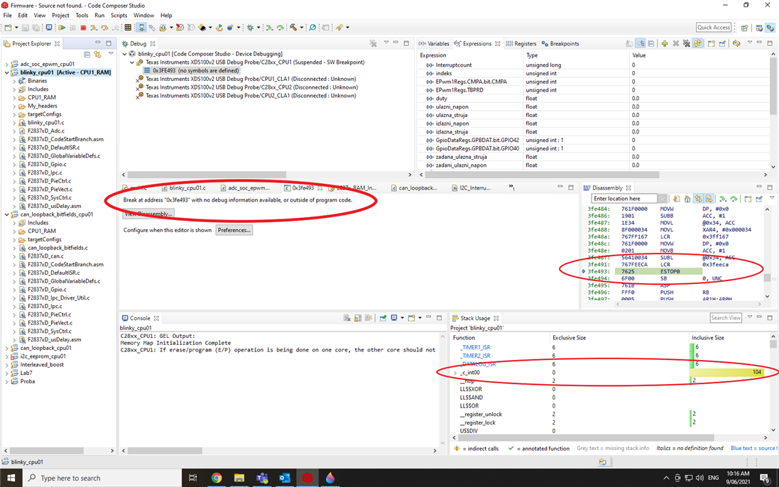
I would like to add here that the program goes through all the initialization succesfully, and also completes the I2C communciation before the infinite for (;;) loop in the main function. This for loop is used for control purposes. A few things I've observed : 

1. Once the program is free running (not using Step into and step through functions), it terminates if the two variables from the  infinite for(;;) loop and the "enable" variable are set to a "1". The enable variable is used for starting the regualtor inside the cpu_timer0_isr, that is to say it starts a lot of computing every control cycle. This worked fine before adding the CAN variables and function declarations.

2. If I comment and/or completely remove the CAN definitions and function declaration, the problem still persists, even though this program worked just fine before adding the CAN stuff. Tried this on a completely factory new processor. Still same issue.

3. I thought this was a stack overflow issue, so I incresed the stack size in Project Properties -> C2000 Linker -> Basic Options ->  Set C system stack size -> 0x400 (the full M1 RAM as defined in the linker)

What are your suggestions for solving this issue? Do you have any general guidelines for writing code that would have prevented this (I use a lot of global variables)?

  • Hi,

    Few more questions that will help me in better understanding of the issue

    1 . Is the code "__asm("  ESTOP0");" added intentionally. Ideally ,this command stops the emulation at this line. This is useful only during debugging but should be removed later on.

    2. What do you mean by the program gets terminated? Does it get stuck at a particular line of code? Can you the call stack to figure out the execution flow?

    3. Ideally the number of global variables should be limited in the code.

    Best Regards

    Siddharth

  • 1. That part of code is added intentionally. As far as I can tell, it didn't cause any problem whatsoever. I was able to single-step through it.

    2. CCS stops the debugger, not allowing me to resume the debug session. From the image above, it seems to be halted at ESTOP0 (at the address 0x3fe493)  as can be seen in the disassembly view.  It gets stuck when it tries to do some computing inside the control loop and the measured values are ≠ 0. How can I call stack to see the execution flow?

    3. I will try to do this in the future. 

  • Hi Emir,

    Is there any reason for using "ESTOP" instruction? Why is it added? the ESTOP instruction works only if you have an emulator connected to the board.

    In case , you want to add  a delay , you can use NOP instruction instead of ESTOP.

    Best Regards

    Siddharth

  • It was used only for debug purposes, and not for delays. I will try running the code without it, but I doubt that is the source of my problem here.

  • Hi ,

    Did you try running without the ESTOP instruction?

    Refer the following thread to see how to check the call stack in CCS

    e2e.ti.com/.../ccs-tms320f28379d-how-do-i-see-the-function-call-stack-function-call-trace-in-code-composer-studio

    Best Regards

    Siddharth

  • 1. I tried running without the ESTOP instructions. During debug one of the variables which control some of the relays on my PCB started getting totally random values assigned to them. This caused the relay contacts to go crazy. I would like to add here : none of this happened before I added definitions of global CAN variables and CAN function prototypes which I have now removed.

    2. Here is the call stack during debug :

    The things I will try to do to solve the issue: 

    1. Try using less global variables

    2. Try using less float type variables

  • Hi, 

    After you removed the ESTOP instruction , did the program break or continued to execute? 

    The variable that you mentioned getting assigned random values -  is it a global variable? 

    The call stack indicates that you are getting timer interrupt while executing from main. You can check the code of this ISR to see if something is causing the variable corruption.

    Best Regards

    Siddharth