
- Ask a related questionWhat is a related question?A related question is a question created from another question. When the related question is created, it will be automatically linked to the original question.
Original question:

TMS320F280025C: SPIA working perfectly fine but SPIB giving lot of errors in data.
Hello,
I'm in the process of integrating an SPI encoder (IC-Haus MU150) to the Launchpad-F28379D
I downloaded C2000Ware and modified the SPI Example project 3 "spi_ex3_external_loopback_fifo_interrupts.c"
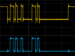
Both in debug-console and Oscilloscope measurements, I see the encoder SOMI (Yellow) echoing in the SIMO line and not sending any useful data back
Also, the SPISTEB pin seems to stay pulled down not making any signals.
Here is the code I am using
Can someone help me spot error in this? Perhaps incorrect logic flow with interrupts?
Thanks
Hansol


