This thread has been locked.
If you have a related question, please click the "Ask a related question" button in the top right corner. The newly created question will be automatically linked to this question.
Hi Expert,
My customer face a strange issue that there will lost some frame data when CAN transmit data in period, they send the data per 400ms in the while loop function, which will include the info of transmit times to check if any frame data is lost.
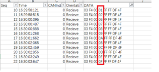
then use CAN tool to capture the data as below, they found that 3rd, 4th, 5th frame data will lost, and did not receive these data by CAN tool.
they connect the CCS for debug, but found no error in LEC register, REC and TEC is also 0, which show no error occur.
Any suggestion for this?
they have follow the guideline "Programming Examples and Debug Strategies for the DCAN Module" to debug, like use 120-Ω resistor, check correct bit time, and use low baud rate, but still did not find the reason.
Hi Strong,
Yes, that seems strange. I see from the time stamp that the messages are spaced about 400ms which is consistent with the loop delay that you indicated and it missed sequence 3,4 and 5. See if customer can do the following since it seems like they can run with CCS in debug mode with the existing setup:
- Add ESTOP0 (or breakpoint) after the 400ms delay in the CAN transmit loop
- While CAN tool is connected, execute F280049 transmitting CAN code by hitting the play button in CCS, this will stop at the breakpoint/ESTOP0 statement which is ok and keep hitting the play button if code reaches breakpoint/ESTOP0.
- At the same time while code is executing/stopping at breakpoint, see if CAN tool is receiving the latest CAN transmission, For every breakpoint or pause in the code, CAN tool should be able to receive a frame from F280049, if not inspect CAN_ES registers to see if there are pending transmissions or errors in LEC while code is stopped.
Point of the above exercise is to see if one-time transmissions are fine as opposed to running the loop. If one-time transmissions are successfully received, we can look at other parts of the code that might be breaking when ran in a loop.
Regards,
Joseph
Hi Joseph,
Thanks for your reply.
customer did the test by inserting breakpoint, the result is the same, LEC did not indicate error and also missed sequence 3,4 and 5.
Hi Strong,
Thanks for that useful debug information. Now, we can monitor IFx contents before they get moved to message ram for transmission. Before code executes CAN_sendMessage (i am assuming customer is using the same dribverlib functions) to transmit the data, can you ask them to look at the contents of the following IFx registers:
- CAN_IFxARB (for correct message ID)
- CAN_IFxDATA (1st 4bytes of data)
- CAN_IFxDATB (2nd 4 bytes of data)
x - 1 or 2 depending on the interface registers used in customer's code
Data should resemble what the customer is intending to transmit (example: 03 F4 00 03 FF FF DF 4F)
Regards,
Joseph
Hi Strong,
Data just shows the first frame where CAN_IF1DATA is 0x0100F403. Can you go further into the breakpoint to see if CAN_IF1DATA will actually reach 0x0300F403 and can you ask customer to also display CAN_IF1DATB for completeness? Would also like to see if CAN_IF1DATA ever will have the other missing values of 0x0400F403 and 0x0500F403.
Thanks,
Joseph
Hi Joseph,
Toady Strong and me are debugging at the customer site, two things update with you:
1.In the previous case, the probability of 0x0100F403 and 0x0300F403 losing data frames is greater than that of 0x0400F403 and 0x0500F403, and there is no change in the registers on CCS between normal sending and abnormal;
2.It is recommended that customers change to the internal clock source of the chip. The loss of CAN frames has improved a lot, but loss of CAN frames still exists.
Do you have any comment on the clock interference that will affect CAN sending data? Or Are there any points that need our attention? thanks!
Hi Joseph,
I find Page 2345 of the TRM as below, If CAN frames is some lost, is there such a situation? if yes, How to configure it? Or do we have a guidebook to use this?
Hi Shaoxing,
Replying to your first post about clock source - can you confirm which clock source is the customer using for SYSCLK/CAN? Is it an external crystal or is it the internal oscillator on the F280049 device? What is the CAN bit rate that the customer is running with and how long is the CAN bus?
Thanks and regards,
Joseph
Hi Joseph,
it is the internal oscillator on the F280049 device, CAN bit rate is 125K, the length of the CAN bus is no more than two meters.
Hi Shaoxing,
The use of INTOSC for CAN communication is not recommended on F280049 device because of the loose specification of INTOSC compared to the strict timing requirement of CAN communications. This is likely the reason for missing frames. Can you check in the customer setup if it is possible to debug the issue by using an external crystal/clock?
Thanks,
Joseph
Hi Shaoxing,
Sorry, not sure what you are referring to, but can you confirm if customer can switch to crystal to debug the problem?
Thanks,
Joseph
Hi Joseph,
yes, the customer switch to the crystal to debug, and it show no error in the register as below:
and don't know how to debug it, can you give us a divr/suggestion?
Hi Joseph,
Customer use the external crystal, the problem also exists
and it show no error in the register, can you help further figure out the root cause?
Hi Shaoxing,
Sorry for responding late as I was on a break for the past couple of days. Is this still an issue at the customer? I noticed in the latest log that you sent that CAN_ES returned a value of '8', which means that the CAN module entered the bus-off state. In bus-off state, CAN is disconnected from the bus and cannot transmit or receive data due to repeated errors. Do you always see this instance of CAN_ES having a value of 8 when the CAN tool does not receive sequences 3,4 and 5?
Thanks.
Joseph