This thread has been locked.

If you have a related question, please click the "Ask a related question" button in the top right corner. The newly created question will be automatically linked to this question.

TMS320F28379D: CMPSS + ECAP accuracy problem measuring frequency

Part Number: TMS320F28379D
Other Parts Discussed in Thread: LAUNCHXL-F28379D, SN74LS14, AMC1200

Hello to everyone,

I'm looking to measure grid frequency using cmpss and ecap module of TMS320F28379D but I've some problem with the accuracy.

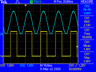
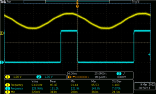
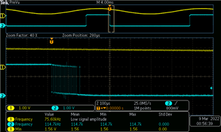
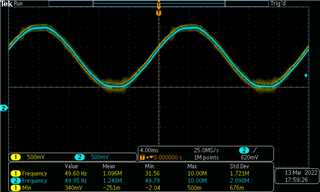
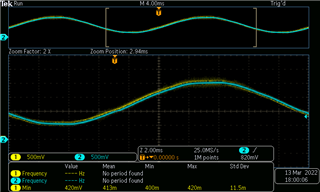
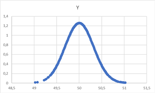
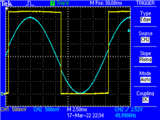
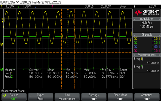
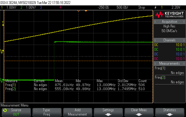
First of all I started with a function generator. I noticed that if the input signal is a square wave (50Hz) the measurement works (with about ±3mHz of error), if I change it to a sine wave signal the error increase a lot (form ±20 to ±50 mHz). I tried to measure also the grid frequency (maybe the connection with function generator wasn't enaough stable) and the results are almost the same. I also tried to change filter and hysteresis parameters but I didn't find a solution.

I think I'm doing something wrong because the peripherics are very fast and the frequency that I've to measure isn't so hight so I'm looking for some help. Or maybe it's necessary some external filter or other stuff (I dont' think so)?

Here's a brief descripton of the code:

The input signal arrives to ADCA4 pin used as a CMPSS (CMPSS2 hight) and hysteresis and digital filter are both configured. For the DAC it was configured a value different from 0 in order to avoid near-zero oscillation.

void initCMPSS(void)
{
    
    CMPSS_enableModule(CMPSS2_BASE);
    CMPSS_configHighComparator(CMPSS2_BASE, CMPSS_INSRC_DAC);

    CMPSS_configDAC(CMPSS2_BASE, CMPSS_DACREF_VDDA | CMPSS_DACVAL_SYSCLK |
                                 CMPSS_DACSRC_SHDW);
    CMPSS_setDACValueHigh(CMPSS2_BASE, 2365);

    CMPSS_setHysteresis(CMPSS2_BASE,4);


    CMPSS_configFilterHigh(CMPSS2_BASE, 0x3FF, 32, 31);


    CMPSS_initFilterHigh(CMPSS2_BASE);


    CMPSS_configOutputsHigh(CMPSS2_BASE, CMPSS_TRIP_FILTER |
                                         CMPSS_TRIPOUT_FILTER);

 
    XBAR_setOutputMuxConfig(XBAR_OUTPUT3, XBAR_OUT_MUX02_CMPSS2_CTRIPOUTH);
    XBAR_enableOutputMux(XBAR_OUTPUT3, XBAR_MUX02);
}

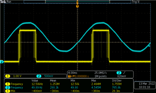
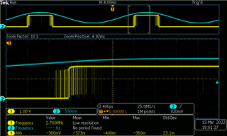
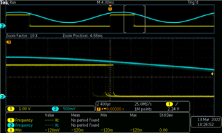
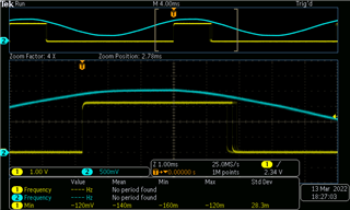
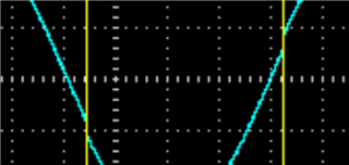
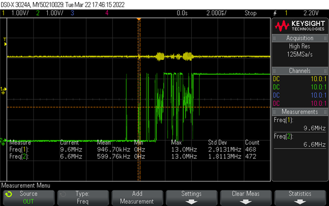
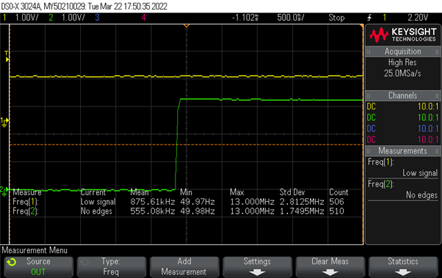
The out of CMPSS goes to xbar3 where a GPIO (14) is connected and, througth this one, is passed to the ECAP. Throught GPIO 14 I can also monitor the output square wave of the ecap (that seems actually a bit "disturbed" in case of sine wave).

The ECAP is configured in one shot mode and capture 2 event (one falling and one rising edge) and the ISR is connected to the second one. The ECAP is re-armed every ISR calling.

void initECAP()
{
    ECAP_disableInterrupt(ECAP1_BASE,
                          (ECAP_ISR_SOURCE_CAPTURE_EVENT_1  |
                           ECAP_ISR_SOURCE_CAPTURE_EVENT_2  |
                           ECAP_ISR_SOURCE_CAPTURE_EVENT_3  |
                           ECAP_ISR_SOURCE_CAPTURE_EVENT_4  |
                           ECAP_ISR_SOURCE_COUNTER_OVERFLOW |
                           ECAP_ISR_SOURCE_COUNTER_PERIOD   |
                           ECAP_ISR_SOURCE_COUNTER_COMPARE));
    ECAP_clearInterrupt(ECAP1_BASE,
                        (ECAP_ISR_SOURCE_CAPTURE_EVENT_1  |
                         ECAP_ISR_SOURCE_CAPTURE_EVENT_2  |
                         ECAP_ISR_SOURCE_CAPTURE_EVENT_3  |
                         ECAP_ISR_SOURCE_CAPTURE_EVENT_4  |
                         ECAP_ISR_SOURCE_COUNTER_OVERFLOW |
                         ECAP_ISR_SOURCE_COUNTER_PERIOD   |
                         ECAP_ISR_SOURCE_COUNTER_COMPARE));


    ECAP_disableTimeStampCapture(ECAP1_BASE);

    ECAP_stopCounter(ECAP1_BASE);
    ECAP_enableCaptureMode(ECAP1_BASE);

    ECAP_setEventPrescaler(ECAP1_BASE,0);

    ECAP_setCaptureMode(ECAP1_BASE, ECAP_ONE_SHOT_CAPTURE_MODE, ECAP_EVENT_2);

    ECAP_setEventPolarity(ECAP1_BASE, ECAP_EVENT_1, ECAP_EVNT_FALLING_EDGE);
    ECAP_setEventPolarity(ECAP1_BASE, ECAP_EVENT_2, ECAP_EVNT_RISING_EDGE);

    ECAP_enableCounterResetOnEvent(ECAP1_BASE, ECAP_EVENT_2);

    XBAR_setInputPin(XBAR_INPUT7, 14);

    ECAP_enableLoadCounter(ECAP1_BASE);
    ECAP_setSyncOutMode(ECAP1_BASE, ECAP_SYNC_OUT_DISABLED);
    ECAP_startCounter(ECAP1_BASE);
    ECAP_enableTimeStampCapture(ECAP1_BASE);
    ECAP_reArm(ECAP1_BASE);

    ECAP_enableInterrupt(ECAP1_BASE, ECAP_ISR_SOURCE_CAPTURE_EVENT_2);
}

__interrupt void ecap1ISR(void)
{
    cap1Count = ECAP_getEventTimeStamp(ECAP1_BASE, ECAP_EVENT_1);
    cap2Count = ECAP_getEventTimeStamp(ECAP1_BASE, ECAP_EVENT_2);

    ECAP_clearInterrupt(ECAP1_BASE,ECAP_ISR_SOURCE_CAPTURE_EVENT_2);

    ECAP_clearGlobalInterrupt(ECAP1_BASE);

    ECAP_reArm(ECAP1_BASE);

    Interrupt_clearACKGroup(INTERRUPT_ACK_GROUP4);
}

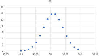
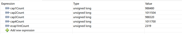
After the ISR I calculate the frequency by dividing the clock (200MHz) by the cap2Count value. I checked in debug mode if it could be a calculation error but the ECAP counter where too much different from the excpected values (for the cap2Count I expect a value of 4000000 but it's different with about ±4000 that correspond to an error of ±50mHz).

Thank you in advance, Gaetano.

Ps. This is my first post, I hope I didn't some mistakes.

  • Hi Gaetano,

    A few questions below:

    1. Is the 50mHz error a standard deviation error or a pk-to-pk error?

    2. What is the source of sysclk? INTOSC or External Clock?

    3. You mentioned the comparator output is being brought out on GPIO. Can you provide a scope shot of this? Be sure to enable frequency measurement and statistics on the scope.

    When capturing a periodic signal like this with the CMPSS, it's best not to use the filter. Using the filter can introduce additional uncertainty in the results. This is due to the memory nature of the filter and how it works. It's fine to enable hysteresis though.

  • Hi Frank,

    thanks for your answer.

    First of all I realized that I didn't say that I'm using LAUNCHXL-F28379D, maybe it's useful.

    I'm going to replay to your questions.

    1. The 50mHz is the pk-to-pk error.

    2. The source of the sysclk is the external clock.

    #define DEVICE_SETCLOCK_CFG         (SYSCTL_OSCSRC_XTAL | SYSCTL_IMULT(40) |  \
                                         SYSCTL_FMULT_NONE | SYSCTL_SYSDIV(2) |   \
                                         SYSCTL_PLL_ENABLE)

    3. This is the scope of the cmpss output taken thorugh GPIO 14 (in yellow) and the input signal (in blue). I attached a screen and a video of the acquisition in order to better explain the little "disturb" I mentioned in the original post. For this scope I used the function generator.

    /cfs-file/__key/communityserver-discussions-components-files/171/VID_5F00_20220309_5F00_184657.mp4

    About the filtering, I added it after finding some problem. For better understanding I'm going to attach some screen.

    I add a screen about the scope of the cmpss output (blue) without filter while measuring grid frequency.

    The following immage is the zoom on the rising edge

    Thanks.

  • Hi Gaetano,

    Thanks for providing the screenshots. In general, capturing a 50Hz sine signal with the CMPSS is always going to be a challenge because the comparator is very fast and doesn't respond well to slow transition signals. Slow transition signals and their noise band tend to take a while to cross the trip region of the comparator. This results in very noisy transitions around the trip region like you are already seeing.

    However, using the CMPSS filter to combat this is not the way if what you care about is frequency accuracy. You will see a lot of jitter in your results. A 50Hz sine is slow enough that you can probably utilize some heavy analog filtering in front of the pin to remove the high frequency noise components. Essentially what you are seeing is expected. 

    Alternatively, have you considered sampling the 50Hz sine with the ADC and performing an FFT instead?

    When you measure the sinewave with the scope, do you also see a 50mHz pk-to-pk error?

  • Hi Frank, 

    thanks for the reply.

    So there are actually some difficult with signals with slow transition.

    We tried with some analog filter but we didn't have good result (the cmpss output has however hight frequency disturbances). Do you think that we could have some improvement using other solutions? (for example analog comparator or converting in some way the sine to square using any component).

    Actually we didn't consider the FFT solution. Can you give me more details on it please?

    On the scope we don't see the 50mHz error.

    Thanks.

  • Hi Gaetono,

    So there are actually some difficult with signals with slow transition.

    True. However this is not unique to the CMPSS on the C2000 device. Most comparators will show this too due to their high bandwidth nature.

    We tried with some analog filter but we didn't have good result (the cmpss output has however hight frequency disturbances)

    Ok. Can you provide more details on what kind of analog filter you tried?

    Do you think that we could have some improvement using other solutions? (for example analog comparator or converting in some way the sine to square using any component).

    Converting the sine to square is actually what you are already doing with the comparator. The ADC and comparator are the only 2 analog inputs on the device.

    Actually we didn't consider the FFT solution. Can you give me more details on it please?

    I checked with a colleague. It should be possible to do this with the ADC but will require taking a large number of samples which will take a long time.

    Did you try all 4 hysteresis values?

    Will it be possible for you to capture a large number of frequency points in order to check the distribution? If the frequency variation is random or normally distributed, you might be able to do some averaging to remove the error

  • Hi Frank,

    Can you provide more details on what kind of analog filter you tried

    We tried with some simple RC filter with various cutting frequency (50 Hz, 100 Hz, 500 Hz, 1kHz, 5 kHz) and, in the best case, we still have spikes around the edges. Do you think we should change filter type?

    Converting the sine to square is actually what you are already doing with the comparator. The ADC and comparator are the only 2 analog inputs on the device.

    Yes I konw, my question was about some other external solution different from filter or comparator we didn't think to.

    Did you try all 4 hysteresis values?

    Actually no, we tried directly with the maximum value given the problems we had. We'll try with other values and I'll let you know about results.

    Will it be possible for you to capture a large number of frequency points in order to check the distribution? If the frequency variation is random or normally distributed, you might be able to do some averaging to remove the error

    I tried also to acquire 2 periods and do the average but nothing change. Unfortunately we need to be so fast in detecting changes (maximum 2 periods) so we can't capture a large number of frequency.

    Thank you again for helping us.

  • Gaetano,

    We tried with some simple RC filter with various cutting frequency (50 Hz, 100 Hz, 500 Hz, 1kHz, 5 kHz) and, in the best case, we still have spikes around the edges. Do you think we should change filter type?

    What were the RC values you tried? Do you have a scope capture of pre and post RC of the waveform that you can provide?

    Yes I konw, my question was about some other external solution different from filter or comparator we didn't think to.

    ADC + FFT is the other way as mentioned above. You can try an external comparator but you will probably see similar sensitivity to noise.

    Actually no, we tried directly with the maximum value given the problems we had. We'll try with other values and I'll let you know about results.

    Ok. If you have already tried the max value then there is no need to try lower values. This actually means the noise is exceeding the max hysteresis value of around 48LSBs. You might want to try an external schmitt trigger configuration to the comparator to increase the hysteresis amount.

    I tried also to acquire 2 periods and do the average but nothing change. Unfortunately we need to be so fast in detecting changes (maximum 2 periods) so we can't capture a large number of frequency.

    I would still like to see this. Can you capture maybe a 1000 frequency samples and look at the distribution? This will give us a good idea if it is random noise or a fixed delta.

  • Hi Frank,

    What were the RC values you tried? Do you have a scope capture of pre and post RC of the waveform that you can provide?

    The RC values were R=100 Ohm and C changing to have different cut frequencies. We tried again with about 1 kHz of cut frequency (R=100 Ohm and C= 1.5 uF) and we obtained the following scope of sine before and after the filter and the scope of the square wave obtained.

    - Sine before (yellow) and after (blue) the filter


    - Square wave


    I would still like to see this. Can you capture maybe a 1000 frequency samples and look at the distribution? This will give us a good idea if it is random noise or a fixed delta.

    We tried to capture 2k samples in three different configurations and these are the distributions (hypotesis of normal distribution):

    - Only with analog filter (R=100 Ohm and C= 1.5 uF)

    Frequency values are too much wrong as you can immagine watching previous scopes

    - Only with digital filter

    - With analog and digital filter

    We have also the scopes in this case:


  • Hi Gaetano,

    The RC values were R=100 Ohm and C changing to have different cut frequencies. We tried again with about 1 kHz of cut frequency (R=100 Ohm and C= 1.5 uF) and we obtained the following scope of sine before and after the filter and the scope of the square wave obtained.

    Filtering should definitely help but I think in your case here, you probably need to get a better idea of your input signal characteristics in order to properly design a filter that removes all the noise you are targeting. A passive RC is just a first order with a slow roll-off. What could be happening here is the filter is not rolling off quick enough to remove all the low magnitude oscillations. You could use the scope to plot an FFT of the sine to see what the spectrum looks like. We can take a look at a few other options before coming back to this.

    - With analog and digital filter

    Thanks for capturing the distribution. This shows that the frequency variation is not a fixed error but rather a normally distributed signal around the 50Hz target. Which means if your application allowed averaging, you could average from a number of samples to get your result.

    Were you able to try the schmitt trigger configuration? You can look at this forum post where a user was doing something similar. I would recommend disabling the internal hysteresis and filter before adding the external schmitt trigger trigger configuration. You will also need to experiment with the feedback resistor values but you can probably start with 100mV hysteresis and work your way from there.

  • Hi Frank,

    Which means if your application allowed averaging, you could average from a number of samples to get your result.

    Unfortunately we need a maximum response time of 50 ms so we can't do an average. We tried with 2 measure (40 ms) but the result doesn't change.

    Were you able to try the schmitt trigger configuration?

    We tried with a TI schmitt trigger with the previous described RC filter. We used SN74LS14 which has a large hysteresis but we didn't have so many advantages. Do you think we need to build a specific trigger?

    At this point we think you are right and we need to build a better filter but if you have any other ideas we can try. If you agree with us, do you have any advice on filter design?

    Thanks

  • Hi Gaetano,

    Unfortunately we need a maximum response time of 50 ms so we can't do an average. We tried with 2 measure (40 ms) but the result doesn't change.

    Ok, I understand. We will look at the other options.

    We tried with a TI schmitt trigger with the previous described RC filter. We used SN74LS14 which has a large hysteresis but we didn't have so many advantages. Do you think we need to build a specific trigger?

    Sorry, that is not what I meant. I wanted you to add a schmitt trigger configuration to the CMPSS i.e connect a feedback resistor from the output i.e GPIO to the Input i.e CMPSS pin. The actual value of the feedback resistor will depend on how much noise is on the sine. You will need to play around with this but you can start with a value that gives you an effective hysteresis of 100mV and then proceed from there. Please be sure to disable the internal hysteresis and filter and also remove the RC so as not to conflate the different knobs. Let us know if this is not clear.

    At this point we think you are right and we need to build a better filter but if you have any other ideas we can try. If you agree with us, do you have any advice on filter design?

    Can you capture an FFT of the sine? Make sure there is enough FFT gain so any potential spurs are visible. This should hopefully let us know if there is a specific frequency or specific sets of frequencies causing this which will help in your filter design.

    P.S Rather than try to correct the issue at the sink, is there anything you can do at the source to make it produce a cleaner sine?

  • Hi Frank,

    Sorry, that is not what I meant. I wanted you to add a schmitt trigger configuration to the CMPSS i.e connect a feedback resistor from the output i.e GPIO to the Input i.e CMPSS pin. The actual value of the feedback resistor will depend on how much noise is on the sine. You will need to play around with this but you can start with a value that gives you an effective hysteresis of 100mV and then proceed from there. Please be sure to disable the internal hysteresis and filter and also remove the RC so as not to conflate the different knobs. Let us know if this is not clear.

    So we have only to add the feedback resistor (R2) between the output GPIO of the cmpss and the input pin of the cmpss or we have also to add the other common resistor (R1) of the schmitt trigger like this:

    We tried with a very large hysteresis and with a couple of resistors R1=220 Ohm and R2=1 kOhm just to try and we didn't have good results. Also we noticed that the sine wave (generated by the function generator) was disturbed (like in the figure):

    Can you capture an FFT of the sine? Make sure there is enough FFT gain so any potential spurs are visible. This should hopefully let us know if there is a specific frequency or specific sets of frequencies causing this which will help in your filter design.

    We didi it and these are the results:

    - From 0 to 50 kHz, 5 kHz/div

    - From 0 to 1.25 kHz, 125 Hz/div

    - From 123.75 kHz to 136.25 kHz, 1.25 kHz/div

    It seems that we have the 50 Hz and the harmonics and the 130 kHz that can create problems. Is it right?

    P.S Rather than try to correct the issue at the sink, is there anything you can do at the source to make it produce a cleaner sine?

    We actually take the grid sine and use a voltage divider and a TI AMC1200 to obtain a sine between 0 and 3 V.

  • Hi Gaetano,

    Are you running the debug experiments with a function generator rather than the signal from the grid in question? If so, can you provide the model number? I will see if i can try to reproduce in the lab with the workarounds.

    Another point is, looking at the resolution you are measuring i.e 50mHz, this is 0.1% of your 50Hz signal. Thinking about this, I'm not sure the CMPSS is accurate enough to do this measurement in one shot without averaging over a number of samples but I'll need to think about this a little more and get back.

    Other responses below.

    So we have only to add the feedback resistor (R2) between the output GPIO of the cmpss and the input pin of the cmpss or we have also to add the other common resistor (R1) of the schmitt trigger like this:

    Yes, this is what i meant.

    We tried with a very large hysteresis and with a couple of resistors R1=220 Ohm and R2=1 kOhm just to try and we didn't have good results.

    This is odd. Hysteresis should make some difference. Is your source impedance into R1 fairly low i.e much less than the 220ohm value? The values you provided should work out to about 0.6v of hysteresis.

    You mentioned not getting good results with the schmitt trigger hysteresis setup. Can you go into a little more detail what didn't work or better yet provide a scope shot of what happens with the feedback resistor over a few cycles.

    Also we noticed that the sine wave (generated by the function generator) was disturbed (like in the figure):

    I didn't quite get what you meant by the "disturbed". Can you explain? Do you mean the trip voltage and untrip voltage are no longer the same? If so, that is expected due to the hysteresis.

    - From 0 to 1.25 kHz, 125 Hz/div

    Got it. Can you capture another one for maybe 0 to 1KHz at 100Hz/div? This will make it easier to read since your fundamental is 50Hz.

    It seems that we have the 50 Hz and the harmonics and the 130 kHz that can create problems. Is it right?

    I don't think you need to go all the way to 130KHz because any LPF you build close to your 50Hz signal will cut-off well before 130KHz.

    We actually take the grid sine and use a voltage divider and a TI AMC1200 to obtain a sine between 0 and 3 V.

    Ok, i see. What is the tolerance of the resistors used for the voltage divider?

  • Hi Frank,

    first of all thanks again for the support. We really appreciate it.

    Are you running the debug experiments with a function generator rather than the signal from the grid in question? If so, can you provide the model number? I will see if i can try to reproduce in the lab with the workarounds

    Actually we are using both. At first we try with TTi TG2000 function generator, than with the real grid (if we think it could be useful).

    This is odd. Hysteresis should make some difference. Is your source impedance into R1 fairly low i.e much less than the 220ohm value? The values you provided should work out to about 0.6v of hysteresis.

    You mentioned not getting good results with the schmitt trigger hysteresis setup. Can you go into a little more detail what didn't work or better yet provide a scope shot of what happens with the feedback resistor over a few cycles

    The output impedance of the cable of the function generator is 50 Ohm. Yes, we've calculated them for an hysteresis value of 0.6 V.

    About not having good results, in debug we noticed that, capturing 2 periods the falling and rising events were almost at the same time (the counters had the same values). So we have thought to have the same problem of the real grid with more edges close together even if in the scope we didn't notice it.

    I didn't quite get what you meant by the "disturbed". Can you explain? Do you mean the trip voltage and untrip voltage are no longer the same? If so, that is expected due to the hysteresis.

    The capture shows that the sine wave in blue has a kind of a little step correspondig to the edges of the square wave:

    Got it. Can you capture another one for maybe 0 to 1KHz at 100Hz/div? This will make it easier to read since your fundamental is 50Hz.

    We'll try to do it on monday and we'll send you the scope

    Ok, i see. What is the tolerance of the resistors used for the voltage divider?

    It should be 1% tolerance.

    Thanks,

    Gaetano

  • Hi Gaetano,

    Actually we are using both. At first we try with TTi TG2000 function generator, than with the real grid (if we think it could be useful).

    Ok. I'll see if i can reproduce this in the lab. You can expect results on this mid to end of next week.

    The output impedance of the cable of the function generator is 50 Ohm. Yes, we've calculated them for an hysteresis value of 0.6 V.

    Ok, that's in line with what I also calculate.

    About not having good results, in debug we noticed that, capturing 2 periods the falling and rising events were almost at the same time (the counters had the same values). So we have thought to have the same problem of the real grid with more edges close together even if in the scope we didn't notice it.

    Sorry, still didn't quite get this. When you did the schmitt trigger hysteresis, what did you get for the frequency?

    The capture shows that the sine wave in blue has a kind of a little step correspondig to the edges of the square wave:

    Ok, I see. I think this is expected. You can view it as R2 is pulling the pos input high during a trip up and pulling it down during a trip down. Since this actually only happens during the trip event, I don't think it's an issue. However if you are concerned, you could probably buffer the input signal to keep it isolated. If you do end up going the low pass filter route, you could build the filter into this buffer to get an active filter. You might need an active filter anyways since so far it looks like the system requires a strong brickwall filter (i.e 2+ stages).

    We'll try to do it on monday and we'll send you the scope

    Ok, sounds good.

    It should be 1% tolerance.

    Ok, I see. 1% should be fine provided the 2 resistors in the divider are matched i.e same make, model etc so you don't end up in a situation where one is changing in one direction while the other is changing in the other direction. We can circle back to this after exploring the other possibilities.

  • Hi Frank,

    Ok. I'll see if i can reproduce this in the lab. You can expect results on this mid to end of next week

    Ok, thanks.

    Sorry, still didn't quite get this. When you did the schmitt trigger hysteresis, what did you get for the frequency?

    The frequency value is very high (also with the function generator). The problem is that we capture close rising/falling events. As you can see the values of the counters aren't what expected. Infact, cap1 should capture the first semi-period (about 2000000), cap2 the first period (about 4000000) and so on (cap3 6000000 and cap4 8000000).

    Ok, I see. I think this is expected. You can view it as R2 is pulling the pos input high during a trip up and pulling it down during a trip down. Since this actually only happens during the trip event, I don't think it's an issue. However if you are concerned, you could probably buffer the input signal to keep it isolated. If you do end up going the low pass filter route, you could build the filter into this buffer to get an active filter. You might need an active filter anyways since so far it looks like the system requires a strong brickwall filter (i.e 2+ stages).

    We was thinking about using the same ADC to read the voltage value so maybe we've to resolve this. But we can think about it later.

    Ok, sounds good.

    Unforunately the minimum value for the division is 125 Hz/div.

  • Hi Gaetano,

    The frequency value is very high (also with the function generator). The problem is that we capture close rising/falling events. As you can see the values of the counters aren't what expected. Infact, cap1 should capture the first semi-period (about 2000000), cap2 the first period (about 4000000) and so on (cap3 6000000 and cap4 8000000).

    Can you provide a screenshot of what the scope shows for this (i.e the frequency of the resulting square wave with hysteresis)?

    We was thinking about using the same ADC to read the voltage value so maybe we've to resolve this. But we can think about it later.

    So since you are very concerned about accuracy here, unless you properly drive the pin, the ADC can cause voltage dips when it samples the pin which can affect the comparator results.

    Unforunately the minimum value for the division is 125 Hz/div.

    Ok, we will have to come back to this.

    ---------------------------------------------------------------------------

    I ran some experiments in the lab using a bench function generator. Results below:

    Setups is as follows: 3.3vpp 50Hz sinewave from function generator fed to positive input of comparator. Comparator trip output comes out on GPIO. Negative input of comparator is driven using internal compdac and set to 1.65. No digital filter used. Device used here is a 100MHz device.

    scope_shot_1: Zoomed out scope capture with no hysteresis. The zoomed out plot looks fine from outward appearance but zoomed in capture below shows that there are multiple transitions around the transition point similar to what you are seeing in your application.

    zoomed_out_no_hysteresis

    scope_shot_2: Zoomed in scope capture of above with no hysteresis. You can see the multiple transitions as expected. Consequently the ECAP also returns garbage values for this.

    zoomed_in_no_hysteresis

    scope_shot_3 and 4: Zoomed in scope capture with 4x hysteresis. All multiple transitions around the trip point have been removed. The signal from the function generator wasn't very noisy so 4x hysteresis was more than enough. This hopefully illustrates to you that hysteresis can solve this issue after you clean up the signal a bit with some LPF.

    zoomed_in_hysteresis_4x_1

    zoomed_in_hysteresis_4x_2

    Ecap results with 4x hysteresis.

    watchwindow_capture

    ECAP is configured to capture rise->fall->rise->fall. It is expected for hysteresis to affect the duty cycle like you can see in the above results but it shouldn't affect the frequency. After adding cap1 to cap2 and cap3 to cap4, I got 50.0004 Hz and 49.9995 Hz for 2 consecutive cycles.

  • Hi Frank,

    so, you suggest us to build a better filter for the sine input of the cmpss, in that way we should be able to obtain results comparable with ones obtained with the function generator.

    Actually, today we've found another possible solution and now we're trying to obtain the square wave as output of a amplifier (like the zero-crossing schemes) and it seems to give acceptable results. (We're thinking to use the LM358AP9)

    At this point I think we're going to compare the two chains (filter+cmpss(with hysteresis)+ecap vs amplifier+ecap) and we'll chose the better one.

    So I think we could consider the issue resolved, am I right? If yes i'll select your prevously reply like the solving one.

    I would like to say thank you to you for all the support you gave to us and I hope this discussion will be useful for someone else.

    Thank you again,

    Gaetano

  • Hi Gaetano,

    so, you suggest us to build a better filter for the sine input of the cmpss, in that way we should be able to obtain results comparable with ones obtained with the function generator.

    Correct. I think a properly designed filter + internal hysteresis of the cmpss should work no problem.

    Actually, today we've found another possible solution and now we're trying to obtain the square wave as output of a amplifier (like the zero-crossing schemes) and it seems to give acceptable results. (We're thinking to use the LM358AP9)

    Ok, I see. The LM358AP is just an opamp and a comparator is indeed a special opamp designed to do one thing. The crux of the issue is that a comparator is too high bandwidth for the very slow 50Hz sine signal. You will have the same issue with the LM358AP in open loop mode. However if you are able to build a close loop around the LM358AP to reduce it's bandwidth significantly, I can see how that would work better.

    At this point I think we're going to compare the two chains (filter+cmpss(with hysteresis)+ecap vs amplifier+ecap) and we'll chose the better one.

    That would be good. You should go with the approach that gives better and more stable results.

    So I think we could consider the issue resolved, am I right? If yes i'll select your prevously reply like the solving one.

    I would like to say thank you to you for all the support you gave to us and I hope this discussion will be useful for someone else.

    Sounds good and glad to help. You can go ahead and mark this thread as resolved. If you ran into anymore issues or neither of the 2 solutions you are exploring works, feel free to create another thread. Best of luck!