This thread has been locked.

If you have a related question, please click the "Ask a related question" button in the top right corner. The newly created question will be automatically linked to this question.

ISR Flow chart for Power supply (1 PFC + 1 STEP-DOWN + 2 LLC) TMS320F28035

Other Parts Discussed in Thread: TMS320F28035

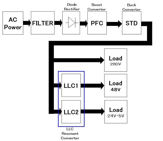
Power supply block as (Fig in below)
     * DSP series is used: once TMS320F28035 (f_osc = 60MHz)
     * Two LLC Resonant(LLC1, LLC2), One STEP-DOWN, One PFC interleaved
        In this case, f_LLC1 differential with f_LLC2
     Detail:
         PFC                 : using 4 ADC channels
         STEP-DOWN : using 1ADC channels
         LLC1               :  using 1 ADC channels
         LLC2               :  using 1 ADC channels
  Could you tell me about ISR flow chart in this case ??

  • Minh,

    What are the switching frequencies involved for each stage?

    Also for LLC, what are the frequency ranges involved? Are you ok with using the CLA?

    Depending on what power stage switching frequency is you can think about time slicing ISR's or have indepdent ISR's, use of CLA would help as that would lessen the burden on the C28x.

    -Manish

  • Hello Manish,

           Switching frepencies for each power stage as following:

                     PFC and STEP-DOWN stages: about 70KHz

                    LLC1, LLC2 Resonant stages: 30KHz to 120 KHz

    With Using the CLA for LLC1, LLC2: I have no expirience about. CLA.  Therefore, First I want the all program running on the CPU.

    Could You tell me about  best ISR flow chart  in this case?

    Regards

  • Minh,

    What control loop frequency do you require for each power stage?  Do you have any estimates on how many CPU cycles each ISR would require?  Without this information, it is hard to give you a "best" case since there are many possibilities.

    If you have sufficient CPU bandwidth to meet the worst case situation (all ISRs executing within the minimum control loop period), you could simply have separate ISRs for each power stage and let them run independently. 

    For example:

    PFC ISR: 200 cycles @ 20 kHz
    Step-Down ISR: 100 cycles @ 50 kHz
    LLC1 ISR: 200 cycles @ 35 kHz
    LLC2 ISR: 200 cycles @ 15 kHz
    Worst case ISR usage: 700 cycles @ 50 kHz

    CPU speed: 60 MHz
    Fastest control loop: 50 kHz
    Worst case bandwidth: 1200 cycles @ 50 kHz

    In this example, because all ISRs can complete execution within the period of the fastest control loop (700 < 1200), no special effort is required.

    Regards,
    Daniel

  • This is not exactly the flowchart I was expecting . This is more like a flow diagram, would love to see standard ones made with flow chart tools