This thread has been locked.

If you have a related question, please click the "Ask a related question" button in the top right corner. The newly created question will be automatically linked to this question.

TMS320F280049C: SPI slave FIFO ISR not working as expected

Part Number: TMS320F280049C

I have additional questions relating to my last posting, "TMS320F280049C: SPI FIFO interrupt".   In my SPI slave application, I want to interrupt only when the FIFO reaches haft full.  I don't want the SPI slave to interrupt for any other reason.  My SPI application is somewhat different in that the slave application does not store or even read data coming from the master.  It only transmits out data to the master and that is controlled by the master's clock and CS.  Please see my code below.  Please see tiff images below.  tiff images can be viewed using Windows Photo Viewer.

Problems:

1;  The first 11 data are not transmitted and the last 4 data are data transmitted from the master.  Please see master com output. 

Sent Data:

    161    178    195    212    229    246    26    43    60    77    94    111    119    136    153

Received Data:

    0    0    0    0    0    0    0    0    0    0    0    77    94    111    119

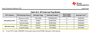
2;  The FIFO haft full ISR triggers 14.10uS after the CS goes high.  Please see 2022-08-08 11_27_37-TEK0016.tiff image.

Obviously, I'm getting the interrupt functions wrong.  Please help.


//##################################################################################################
//
// TITLE:  10mm_Data_Output_fifo_interrupts
//
//! This program uses the two SPI modules. Both the SPI FIFOs and their interrupts are used.
//! SPIA is configured as a slave and transmits data to a master TIVA on the MFC control board.
//! SPI B is configured as a master and receives data from the ADS2161 on the 10mm_Top-hat board.
//!
//! The 10mm_Top-hat board will send a DRDY (data ready) positive pulse of between 50uS and 100uS.
//! The falling edge will trigger a interrupt in the master TIVA on the MFC control board.
//!
//!  External Connections
//! -GPIO24 and GPIO16 - SPISIMO    GPIO24 is pin 75 and GPIO16 is pin 67 on the 120 pin edge connector.  GPIO24 is set to pin 75 through S5 in the default setting.
//! -GPIO31 and GPIO17 - SPISOMI    GPIO31 is pin 74 and GPIO17 is pin 69 on the 120 pin edge connector.
//! -GPIO22 and GPIO56 - SPICLK     GPIO22 is pin 72 and GPIO56 is pin 103 on the 120 pin edge connector.
//! -GPIO27 and GPIO57 - SPISTE     GPIO27 is pin 81 and GPIO57 is pin 70 on the 120 pin edge connector.  GPIO27 is set to pin 81 through S6 in the default setting.
//!
//#################################################################################################

//
// Included Files
//
#include "driverlib.h"
#include "device.h"
#include "board.h"

#define numData 40

typedef unsigned char   uint8_t;

//
// Globals
//
volatile uint16_t sData[numData];   // Send data buffer

static uint16_t DataPtr = 0;
static bool interruptFlag = true;

//#######################################################################################
// Slave output data.
// See "Proposal SPI Communication Protocol for Keller Pressure Sensor.docx" on the WIKI.
// Will be implemented later.
//
// This union is used to send floating point data over the SPI.
//
union {
    uint32_t    Integer;
    float       Float;
} cpd,  // CalculatedPressureData Pressure range is 0 torr to 2585.75 torr
  ctd,  // CalculatedTemeratureData Temperature range is 15°C to 45°C
  sfs,  // SensorFullScale For the TE 85U, the sfs is 2585.75 torr (50psi)
  szs;  // SensorZeroScale For the TE 85U, the sfs is 0 torr

uint8_t statusByte;
uint32_t serialNum;
uint8_t pressureMode;
uint16_t pollingRate;
char productNum[16];

//#######################################################################################

//
// Function Prototypes
//
__interrupt void spiaTxFIFO_ISR(void);

//
// Main
//
void main(void)
{
    //
    // Initialize device clock and peripherals
    //
    Device_init();

    //
    // Disable pin locks and enable internal pull-ups.
    //
    Device_initGPIO();

    //
    // Board initialization
    //
    Board_init();

    //
    // Initialize PIE and clear PIE registers. Disables CPU interrupts.
    //
    Interrupt_initModule();

    //
    // Initialize the PIE vector table with pointers to the shell Interrupt
    // Service Routines (ISR).
    //
    Interrupt_initVectorTable();

    //
    // Interrupts that are used in this example are re-mapped to ISR functions
    // found within this file.
    //
    Interrupt_register(INT_SPIA_TX, &spiaTxFIFO_ISR);

    //
    // Clear SPI receive and transmit buffers
    //
    SPI_reset(SPIA_slave_BASE);


    //
    // Transmit data initialization.  Because the transmit and receive data
    // length is 8 bits and the MSB is transmitted first, this initialization pre-shifts the data.
    //
    sData[0] = 0x0100;      // 1 dec
    sData[1] = 0x0200;      // 2 dec
    sData[2] = 0x0400;      // 4 dec
    sData[3] = 0x0800;      // 8 dec
    sData[4] = 0x1000;      // 16 dec
    sData[5] = 0x2000;      // 32 dec
    sData[6] = 0x4000;      // 64 dec
    sData[7] = 0x8000;      // 128 dec
    sData[8] = 0x1100;      // 17 dec
    sData[9] = 0x1200;      // 18 dec
    sData[10] = 0x1400;     // 20 dec
    sData[11] = 0x1800;     // 24 dec
    sData[12] = 0x2100;     // 33 dec
    sData[13] = 0x2200;     // 34 dec
    sData[14] = 0x2400;     // 36 dec
    sData[15] = 0x2800;     // 40 dec
    sData[16] = 0x4100;     // 65 dec
    sData[17] = 0x4200;     // 66 dec
    sData[18] = 0x4400;     // 68 dec
    sData[19] = 0x4800;     // 72 dec

    //
    // Enable Global Interrupt (INTM) and Realtime Interrupt (DBGM)
    //
    EINT;       // Does the same thing that Interrupt_enableMaster().
    ERTM;       // enables debug events

    //
    // Preload SPI slave output buffer.
    // This is required because the output buffer must have something in it
    // so when the SPI A slave receive ISR triggers, it will have something
    // transmit.  The resulting ISR will preload the next slave output data
    // for the next ISR.
    //

    //
    // Loop forever.
    //
    while(1)
    {
        if(GPIO_readPin(57) & interruptFlag)    // GPIO_readPin(57) returns the value of GPIO57 which is the CS of the SPIA module.
        {                                       // If true (high) then the SPIA has not been selected.
            //
            // Disable the SPIA interrupt for Rx events.
            //
            Interrupt_disable(INT_SPIA_TX);
            SPI_disableInterrupt(SPIA_BASE, SPI_INT_TXFF);
            SPI_disableFIFO(SPIA_slave_BASE);   // disabling and enabling FIFO resets FIFO data to 0.
            SPI_enableFIFO(SPIA_slave_BASE);
            SPI_reset(SPIA_slave_BASE);     // Clear SPI receive and transmit buffers

            interruptFlag = false;

            for(DataPtr = 0; DataPtr < 16; DataPtr++)                   // This loop preloads the output FIFO of the slave SPIA before the
            {                                                           // slave SPIA is selected.  The SPIA FIFPO is 16 words deep. DataPtr
                SPI_writeDataNonBlocking(SPIA_BASE, (sData[DataPtr]));  // is a global static variable and will be used in the FIFO interrupt.
            }

            //
            // Enable the SPIA interrupt for Rx events.
            //
            //

            Interrupt_enable(INT_SPIA_TX);      // Enable SPIA interrupt in the PIE: Group 6
            SPI_enableInterrupt(SPIA_BASE, SPI_INT_TXFF);   // Enable the SPIA interrupt for Tx and Rx events.

        }
        else if(!GPIO_readPin(57) & !interruptFlag)     // If GPIO_readPin(57) and interruptFlag are false, then the SPIA slave is active.
        {
            interruptFlag = true;   // Set the interruptFlag = true in preparation to reload the SIPA slave FIFO for new data transfer.
        }
    }
}


//
// SPI A slave TX FIFO ISR
// This interrupt is triggered because the slave TX FIFO
// status has reached the FIFO trigger level.
//
 __interrupt void spiaTxFIFO_ISR(void)
{
     uint16_t i;
     GPIO_writePin(myGPIOPin57, false);    // Oscilloscope timing signal
    //
    // write data
    //
     for(i = 0; i < 8; i++)
     {
         SPI_writeDataNonBlocking(SPIA_BASE, (sData[DataPtr]));    // This is preloading the output FIFO.

         DataPtr++;
     }

    //
    // Clear interrupt flag and issue ACK
    //
    SPI_clearInterruptStatus(SPIA_BASE, SPI_INT_RX_DATA_TX_EMPTY);
    Interrupt_clearACKGroup(INTERRUPT_ACK_GROUP6);
    GPIO_writePin(myGPIOPin57, true);    // Oscilloscope timing signal
}
  

/*
 * Copyright (c) 2020 Texas Instruments Incorporated - http://www.ti.com
 * All rights reserved.
 *
 * Redistribution and use in source and binary forms, with or without
 * modification, are permitted provided that the following conditions
 * are met:
 *
 * *  Redistributions of source code must retain the above copyright
 *    notice, this list of conditions and the following disclaimer.
 *
 * *  Redistributions in binary form must reproduce the above copyright
 *    notice, this list of conditions and the following disclaimer in the
 *    documentation and/or other materials provided with the distribution.
 *
 * *  Neither the name of Texas Instruments Incorporated nor the names of
 *    its contributors may be used to endorse or promote products derived
 *    from this software without specific prior written permission.
 *
 * THIS SOFTWARE IS PROVIDED BY THE COPYRIGHT HOLDERS AND CONTRIBUTORS "AS IS"
 * AND ANY EXPRESS OR IMPLIED WARRANTIES, INCLUDING, BUT NOT LIMITED TO,
 * THE IMPLIED WARRANTIES OF MERCHANTABILITY AND FITNESS FOR A PARTICULAR
 * PURPOSE ARE DISCLAIMED. IN NO EVENT SHALL THE COPYRIGHT OWNER OR
 * CONTRIBUTORS BE LIABLE FOR ANY DIRECT, INDIRECT, INCIDENTAL, SPECIAL,
 * EXEMPLARY, OR CONSEQUENTIAL DAMAGES (INCLUDING, BUT NOT LIMITED TO,
 * PROCUREMENT OF SUBSTITUTE GOODS OR SERVICES; LOSS OF USE, DATA, OR PROFITS;
 * OR BUSINESS INTERRUPTION) HOWEVER CAUSED AND ON ANY THEORY OF LIABILITY,
 * WHETHER IN CONTRACT, STRICT LIABILITY, OR TORT (INCLUDING NEGLIGENCE OR
 * OTHERWISE) ARISING IN ANY WAY OUT OF THE USE OF THIS SOFTWARE,
 * EVEN IF ADVISED OF THE POSSIBILITY OF SUCH DAMAGE.
 *
 */

#include "board.h"

void Board_init()
{
	EALLOW;

	PinMux_init();
	GPIO_init();
	SPI_init();

	EDIS;
}

void PinMux_init()
{
	// GPIO25 -> myGPIOPin57 Pinmux
	GPIO_setPinConfig(GPIO_25_GPIO25);
	//
	// SPIA -> SPIA_slave Pinmux
	//
	GPIO_setPinConfig(GPIO_16_SPIA_SIMO);
	GPIO_setPinConfig(GPIO_17_SPIA_SOMI);
	GPIO_setPinConfig(GPIO_56_SPIA_CLK);
	GPIO_setPinConfig(GPIO_57_SPIA_STE);

}

void GPIO_init(){
		
	//myGPIOPin57 initialization
	GPIO_setDirectionMode(myGPIOPin57, GPIO_DIR_MODE_OUT);
	GPIO_setPadConfig(myGPIOPin57, GPIO_PIN_TYPE_PULLUP);
	GPIO_setMasterCore(myGPIOPin57, GPIO_CORE_CPU1);
	GPIO_setQualificationMode(myGPIOPin57, GPIO_QUAL_ASYNC);
}
void SPI_init()
{
	
	//SPIA_slave initialization
	SPI_disableModule(SPIA_slave_BASE);
	SPI_setConfig(SPIA_slave_BASE, DEVICE_LSPCLK_FREQ, SPI_PROT_POL0PHA1,
				  SPI_MODE_SLAVE, 1000000, 	8);
	SPI_enableFIFO(SPIA_slave_BASE);
	SPI_setFIFOInterruptLevel(SPIA_slave_BASE, SPI_FIFO_TX8, SPI_FIFO_RX8);
	SPI_clearInterruptStatus(SPIA_slave_BASE, SPI_INT_TXFF);
	SPI_enableInterrupt(SPIA_slave_BASE, SPI_INT_TXFF);
	SPI_disableLoopback(SPIA_slave_BASE);
	SPI_setEmulationMode(SPIA_slave_BASE, SPI_EMULATION_FREE_RUN);
	SPI_enableModule(SPIA_slave_BASE);
}

2022-08-08 11_15_42-TEK0015.tiff     2022-08-08 11_27_37-TEK0016.tiff     2022-08-08 11_32_54-TEK0017.tiff

  • What exactly are you trying inside your while(1)? I want to know why you are reading GPIO57 and interrupt flag.

  • Dear Manoj

    The if statement inside the while loop is there to reset the data pointer back to zero and clear all FIFO and output register data in preparation for the next master data request.  I watch GPIO57 because it is the CS for the SPIA slave.  The sdata array's data is already left shifted 8 places.  This brings up another question.  A colleague of mine suggested because the data size is 8 bits that the FIFO is actually a 32 byte FIFO as apposed to a 16 word (2-byte) FIFO.  Am I loading the FIFO correctly?

  • SPI has only 16 word FIFO. When are working on a transaction, you left shift a byte by 8.

    For example: to Tranmit 0x005A, you will right shift by 0x5A << 8 and stores as 0x5A00 in FIFO Transmit buffer.

  • Dear Manoj

    So, as I understand, for a 8bit data size, when the SPIA slave gets 8 clocks from the SPI master, the MSB is transmitted out of the SPIDAT register and then the SPITXBUF and SPIDAT registers get zeroed.  Is this correct?  In addition, each time I write to the TX FIFO, regardless of the data size, the entire FIFO word is used.  That is, if the data size is 4 bits and I write 6 data to the FIFO, 6 FIFO words are used.  Is this correct?  

  • Yes, your understanding is correct

  • Dear Manoj

    I've simplified my code to get a better understanding of the FIFO interrupt system.  See attached code.  Note that I've commented out all of the if statement in the while loop and placed a one time preloading of the FIFO above the while loop.  I've also placed a break point in the FIFO ISR.  When I run this code in the debugger, instead of waiting in the while loop, because there is no CS or clock from the master, it goes directly to the FIFO ISR break point.  In the SPIFFTX register it shows the TXFFST register is greater than the TXFFIL register and the TXFFINT flag is clear.  Please see register image below.  Do you have any reason for this action?  

    ##################################################################################################
    //
    // TITLE:  10mm_Data_Output_fifo_interrupts
    //
    //! This program uses the two SPI modules. Both the SPI FIFOs and their interrupts are used.
    //! SPIA is configured as a slave and transmits data to a master TIVA on the MFC control board.
    //! SPI B is configured as a master and receives data from the ADS2161 on the 10mm_Top-hat board.
    //!
    //! The 10mm_Top-hat board will send a DRDY (data ready) positive pulse of between 50uS and 100uS.
    //! The falling edge will trigger a interrupt in the master TIVA on the MFC control board.
    //!
    //!  External Connections
    //! -GPIO24 and GPIO16 - SPISIMO    GPIO24 is pin 75 and GPIO16 is pin 67 on the 120 pin edge connector.  GPIO24 is set to pin 75 through S5 in the default setting.
    //! -GPIO31 and GPIO17 - SPISOMI    GPIO31 is pin 74 and GPIO17 is pin 69 on the 120 pin edge connector.
    //! -GPIO22 and GPIO56 - SPICLK     GPIO22 is pin 72 and GPIO56 is pin 103 on the 120 pin edge connector.
    //! -GPIO27 and GPIO57 - SPISTE     GPIO27 is pin 81 and GPIO57 is pin 70 on the 120 pin edge connector.  GPIO27 is set to pin 81 through S6 in the default setting.
    //!
    //#################################################################################################
    
    //
    // Included Files
    //
    #include "driverlib.h"
    #include "device.h"
    #include "board.h"
    
    #define numData 40
    
    typedef unsigned char   uint8_t;
    
    //
    // Globals
    //
    volatile uint16_t sData[numData];   // Send data buffer
    
    static uint16_t DataPtr = 0;
    static bool interruptFlag = true;
    
    //#######################################################################################
    //! Slave output data.
    //! See "Proposal SPI Communication Protocol for Keller Pressure Sensor.docx" on the WIKI.
    //! Will be implemented later.
    //
    // This union is used to send floating point data over the SPI.
    //
    union {
        uint32_t    Integer;
        float       Float;
    } cpd,  // CalculatedPressureData Pressure range is 0 torr to 2585.75 torr
      ctd,  // CalculatedTemeratureData Temperature range is 15°C to 45°C
      sfs,  // SensorFullScale For the TE 85U, the sfs is 2585.75 torr (50psi)
      szs;  // SensorZeroScale For the TE 85U, the sfs is 0 torr
    
    uint8_t statusByte;
    uint32_t serialNum;
    uint8_t pressureMode;
    uint16_t pollingRate;
    char productNum[16];
    
    //#######################################################################################
    
    //
    // Function Prototypes
    //
    __interrupt void spiaTxFIFO_ISR(void);
    
    //
    // Main
    //
    void main(void)
    {
        //
        // Initialize device clock and peripherals
        //
        Device_init();
    
        //
        // Disable pin locks and enable internal pull-ups.
        //
        Device_initGPIO();
    
        //
        // Initialize PIE and clear PIE registers. Disables CPU interrupts.
        //
        Interrupt_initModule();
    
        //
        // Initialize the PIE vector table with pointers to the shell Interrupt
        // Service Routines (ISR).
        //
        Interrupt_initVectorTable();
    
        //
        // Interrupts that are used in this example are re-mapped to ISR functions
        // found within this file.
        //
        Interrupt_register(INT_SPIA_TX, &spiaTxFIFO_ISR);
    
        //
        // Board initialization
        //
        Board_init();
    
        //
        // Clear SPI receive and transmit buffers
        //
        SPI_reset(SPIA_slave_BASE);
    
    
        //
        // Transmit data initialization.  Because the transmit and receive data
        // length is 8 bits and the MSB is transmitted first, this initialization pre-shifts the data.
        //
        sData[0] = 0x0100;      // 1 dec
        sData[1] = 0x0200;      // 2 dec
        sData[2] = 0x0400;      // 4 dec
        sData[3] = 0x0800;      // 8 dec
        sData[4] = 0x1000;      // 16 dec
        sData[5] = 0x2000;      // 32 dec
        sData[6] = 0x4000;      // 64 dec
        sData[7] = 0x8000;      // 128 dec
        sData[8] = 0x1100;      // 17 dec
        sData[9] = 0x1200;      // 18 dec
        sData[10] = 0x1400;     // 20 dec
        sData[11] = 0x1800;     // 24 dec
        sData[12] = 0x2100;     // 33 dec
        sData[13] = 0x2200;     // 34 dec
        sData[14] = 0x2400;     // 36 dec
        sData[15] = 0x2800;     // 40 dec
        sData[16] = 0x4100;     // 65 dec
        sData[17] = 0x4200;     // 66 dec
        sData[18] = 0x4400;     // 68 dec
        sData[19] = 0x4800;     // 72 dec
    
        //
        // Preload SPI slave output buffer.
        // This is required because the output buffer must have something in it
        // so when the SPI A slave receive ISR triggers, it will have something
        // to transmit.  The resulting ISR will preload the next slave output data
        // for the next ISR.
        //
    
    
        for(DataPtr = 0; DataPtr < 16; DataPtr++)                   // This loop preloads the output FIFO of the slave SPIA before the
        {                                                           // slave SPIA is selected.  The SPIA FIFPO is 16 words deep. DataPtr
            SPI_writeDataNonBlocking(SPIA_BASE, (sData[DataPtr]));  // is a global static variable and will be used in the FIFO interrupt.
        }
    
        SPI_clearInterruptStatus(SPIA_BASE, SPI_INT_TXFF);
        Interrupt_clearACKGroup(INTERRUPT_ACK_GROUP6);
        Interrupt_enable(INT_SPIA_TX);      // Enable SPIA interrupt in the PIE: Group 6
    
        //
        // Enable Global Interrupt (INTM) and Realtime Interrupt (DBGM)
        //
        EINT;       // Does the same thing that Interrupt_enableMaster().
        ERTM;       // enables debug events


        //
        // Loop forever.
        //
        while(1)
        {
    /*        if(GPIO_readPin(57) & interruptFlag)    // GPIO_readPin(57) returns the value of GPIO57 which is the CS of the SPIA module.
            {                                       // If true (high) then the SPIA has not been selected.
                //
                // Disable the SPIA interrupt for Rx events.
                //
                Interrupt_disable(INT_SPIA_TX);
                SPI_disableInterrupt(SPIA_BASE, SPI_INT_TXFF);
                SPI_disableFIFO(SPIA_slave_BASE);   // disabling and enabling FIFO resets FIFO data to 0.
                SPI_enableFIFO(SPIA_slave_BASE);
                SPI_reset(SPIA_slave_BASE);     // Clear SPI receive and transmit buffers
    
                interruptFlag = false;
    
                for(DataPtr = 0; DataPtr < 16; DataPtr++)                   // This loop preloads the output FIFO of the slave SPIA before the
                {                                                           // slave SPIA is selected.  The SPIA FIFPO is 16 words deep. DataPtr
                    SPI_writeDataNonBlocking(SPIA_BASE, (sData[DataPtr]));  // is a global static variable and will be used in the FIFO interrupt.
                }
    
                //
                // Enable the SPIA interrupt for Rx events.
                //
                //
    
                Interrupt_enable(INT_SPIA_TX);      // Enable SPIA interrupt in the PIE: Group 6
                SPI_enableInterrupt(SPIA_BASE, SPI_INT_TXFF);   // Enable the SPIA interrupt for Tx and Rx events.
    
            }
            else if(!GPIO_readPin(57) & !interruptFlag)     // If GPIO_readPin(57) and interruptFlag are false, then the SPIA slave is active.
            {
                interruptFlag = true;   // Set the interruptFlag = true in preparation to reload the SIPA slave FIFO for new data transfer.
            }*/
        }
    }
    
    
    //
    // SPI A slave TX FIFO ISR
    // This interrupt is triggered because the slave TX FIFO
    // status has reached the FIFO trigger level.
    //
     __interrupt void spiaTxFIFO_ISR(void)
    {
         uint16_t i;
         GPIO_writePin(myGPIOPin57, false);    // Oscilloscope timing signal
        //
        // write data
        //
         for(i = 0; i < 8; i++)
         {
             SPI_writeDataNonBlocking(SPIA_BASE, (sData[DataPtr]));    // This is preloading the output FIFO.
    
             DataPtr++;
         }
    
        //
        // Clear interrupt flag and issue ACK
        //
        SPI_clearInterruptStatus(SPIA_BASE, SPI_INT_RX_DATA_TX_EMPTY);
        Interrupt_clearACKGroup(INTERRUPT_ACK_GROUP6);
        GPIO_writePin(myGPIOPin57, true);    // Oscilloscope timing signal
    }
    

    SpiaRegs SPI Registers
    SPICCR                   0x0087                    SPI Configuration Control Register [Memory Mapped]
    SPICTL                    0x000A                    SPI Operation Control Register [Memory Mapped]
    SPISTS                    0x0000                    SPI Status Register [Memory Mapped]
    SPIBRR                   0x0018                    SPI Baud Rate Register [Memory Mapped]
    SPIRXEMU              0x0000                   SPI Emulation Buffer Register [Memory Mapped]
    SPIRXBUF               0x11CE                   SPI Serial Input Buffer Register [Memory Mapped]
    SPITXBUF               0x2800                    SPI Serial Output Buffer Register [Memory Mapped]
    SPIDAT                     0x0100                   SPI Serial Data Register [Memory Mapped]
    SPIFFTX                  0xEF28                   SPI FIFO Transmit Register [Memory Mapped]
        SPIRST                1                             SPI Reset
        SPIFFENA            1                             FIFO Enhancements Enable
        TXFIFO                 1                             TXFIFO Reset
        TXFFST                01111                      Transmit FIFO Status
        TXFFINT               0                             TXFIFO Interrupt Flag
        TXFFINTCLR        0                             TXFIFO Interrupt Clear
        TXFFIENA            1                              TXFIFO Interrupt Enable
        TXFFIL                 01000                      TXFIFO Interrupt Level
    SPIFFRX                 0x2008                     S PI FIFO Receive Register [Memory Mapped]
    SPIFFCT                 0x0000                     SPI FIFO Control Register [Memory Mapped]
    SPIPRI                    0x0010                     SPI Priority Control Register [Memory Mapped]

  • Dear Manoj

    Here is some additional information.  I set a break point at the EINT; line in my code.  Please see IER and IFR register before and after images below.  Notice not only the group 6 IER is set but now the group 6 IFR is set.  What caused this interrupt flag to be set?  

    BEFORE                                                                                 AFTER


  • IFR.INT6 might be set because of the interrupt from SPI based on your configuration.

  • Dear Manoj

    Yes, I believe you're correct.  I've been digging deeper into the registers, memory and SPI setup process.  Please see code below.  This code was generated by the .syscfg GUI.  Please note the SPI_init() function.  The Board_init() function is called before i've initialized the FIFO, (I can't initialize the FIFO before the SPI is enabled).  As a result, when the SPI_enableInterrupt(SPIA_slave_BASE, SPI_INT_TXFF) fuction is called, the TX FIFO interrupt is triggered.  Not only is the TXFFINT Interrupt Flag set in the SPIFFTX register, the INT6 Interrupt 6 flag is set.  After returning from the Board_init() function, I initialize the FIFO.  I then clear the SPI and group 6 interrupts by calling the SPI_clearInterruptStatus(SPIA_BASE, SPI_INT_TXFF) and Interrupt_clearACKGroup(INTERRUPT_ACK_GROUP6) functions.  I believe this should clear all related interrupts.  However, when I run the code in the debugger and break at the EINT (global interrupt enable), the group 6 interrupt flag does not clear.  I've tried putting the interrupt clear functions after the Interrupt_enable(INT_SPIA_TX) function.  It made no difference.  Why is the group 6 interrupt flag not clearing?  

    /*
     * Copyright (c) 2020 Texas Instruments Incorporated - http://www.ti.com
     * All rights reserved.
     *
     * Redistribution and use in source and binary forms, with or without
     * modification, are permitted provided that the following conditions
     * are met:
     *
     * *  Redistributions of source code must retain the above copyright
     *    notice, this list of conditions and the following disclaimer.
     *
     * *  Redistributions in binary form must reproduce the above copyright
     *    notice, this list of conditions and the following disclaimer in the
     *    documentation and/or other materials provided with the distribution.
     *
     * *  Neither the name of Texas Instruments Incorporated nor the names of
     *    its contributors may be used to endorse or promote products derived
     *    from this software without specific prior written permission.
     *
     * THIS SOFTWARE IS PROVIDED BY THE COPYRIGHT HOLDERS AND CONTRIBUTORS "AS IS"
     * AND ANY EXPRESS OR IMPLIED WARRANTIES, INCLUDING, BUT NOT LIMITED TO,
     * THE IMPLIED WARRANTIES OF MERCHANTABILITY AND FITNESS FOR A PARTICULAR
     * PURPOSE ARE DISCLAIMED. IN NO EVENT SHALL THE COPYRIGHT OWNER OR
     * CONTRIBUTORS BE LIABLE FOR ANY DIRECT, INDIRECT, INCIDENTAL, SPECIAL,
     * EXEMPLARY, OR CONSEQUENTIAL DAMAGES (INCLUDING, BUT NOT LIMITED TO,
     * PROCUREMENT OF SUBSTITUTE GOODS OR SERVICES; LOSS OF USE, DATA, OR PROFITS;
     * OR BUSINESS INTERRUPTION) HOWEVER CAUSED AND ON ANY THEORY OF LIABILITY,
     * WHETHER IN CONTRACT, STRICT LIABILITY, OR TORT (INCLUDING NEGLIGENCE OR
     * OTHERWISE) ARISING IN ANY WAY OUT OF THE USE OF THIS SOFTWARE,
     * EVEN IF ADVISED OF THE POSSIBILITY OF SUCH DAMAGE.
     *
     */
    
    #include "board.h"
    
    void Board_init()
    {
    	EALLOW;
    
    	PinMux_init();
    	GPIO_init();
    	SPI_init();
    
    	EDIS;
    }
    
    void PinMux_init()
    {
    	// GPIO25 -> myGPIOPin57 Pinmux
    	GPIO_setPinConfig(GPIO_25_GPIO25);
    	//
    	// SPIA -> SPIA_slave Pinmux
    	//
    	GPIO_setPinConfig(GPIO_16_SPIA_SIMO);
    	GPIO_setPinConfig(GPIO_17_SPIA_SOMI);
    	GPIO_setPinConfig(GPIO_56_SPIA_CLK);
    	GPIO_setPinConfig(GPIO_57_SPIA_STE);
    
    }
    
    void GPIO_init(){
    		
    	//myGPIOPin57 initialization
    	GPIO_setDirectionMode(myGPIOPin57, GPIO_DIR_MODE_OUT);
    	GPIO_setPadConfig(myGPIOPin57, GPIO_PIN_TYPE_PULLUP);
    	GPIO_setMasterCore(myGPIOPin57, GPIO_CORE_CPU1);
    	GPIO_setQualificationMode(myGPIOPin57, GPIO_QUAL_ASYNC);
    }
    void SPI_init()
    {
    	
    	//SPIA_slave initialization
    	SPI_disableModule(SPIA_slave_BASE);
    	SPI_setConfig(SPIA_slave_BASE, DEVICE_LSPCLK_FREQ, SPI_PROT_POL0PHA1,
    				  SPI_MODE_SLAVE, 1000000, 	8);
    	SPI_enableFIFO(SPIA_slave_BASE);
    	SPI_setFIFOInterruptLevel(SPIA_slave_BASE, SPI_FIFO_TX8, SPI_FIFO_RX8);
    	SPI_clearInterruptStatus(SPIA_slave_BASE, SPI_INT_TXFF);
    	SPI_enableInterrupt(SPIA_slave_BASE, SPI_INT_TXFF);
    	SPI_disableLoopback(SPIA_slave_BASE);
    	SPI_setEmulationMode(SPIA_slave_BASE, SPI_EMULATION_FREE_RUN);
    	SPI_enableModule(SPIA_slave_BASE);
    }
    

        Board_init();
    
        //
        // Clear SPI receive and transmit buffers
        //
        SPI_reset(SPIA_slave_BASE);
    
    
        //
        // Transmit data initialization.  Because the transmit and receive data
        // length is 8 bits and the MSB is transmitted first, this initialization pre-shifts the data.
        //
        sData[0] = 0x0100;      // 1 dec
        sData[1] = 0x0200;      // 2 dec
        sData[2] = 0x0400;      // 4 dec
        sData[3] = 0x0800;      // 8 dec
        sData[4] = 0x1000;      // 16 dec
        sData[5] = 0x2000;      // 32 dec
        sData[6] = 0x4000;      // 64 dec
        sData[7] = 0x8000;      // 128 dec
        sData[8] = 0x1100;      // 17 dec
        sData[9] = 0x1200;      // 18 dec
        sData[10] = 0x1400;     // 20 dec
        sData[11] = 0x1800;     // 24 dec
        sData[12] = 0x2100;     // 33 dec
        sData[13] = 0x2200;     // 34 dec
        sData[14] = 0x2400;     // 36 dec
        sData[15] = 0x2800;     // 40 dec
        sData[16] = 0x4100;     // 65 dec
        sData[17] = 0x4200;     // 66 dec
        sData[18] = 0x4400;     // 68 dec
        sData[19] = 0x4800;     // 72 dec
    
        //
        // Preload SPI slave output buffer.
        // This is required because the output buffer must have something in it
        // so when the SPI A slave receive ISR triggers, it will have something
        // to transmit.  The resulting ISR will preload the next slave output data
        // for the next ISR.
        //
    
    
        for(DataPtr = 0; DataPtr < 16; DataPtr++)                   // This loop preloads the output FIFO of the slave SPIA before the
        {                                                           // slave SPIA is selected.  The SPIA FIFPO is 16 words deep. DataPtr
            SPI_writeDataNonBlocking(SPIA_BASE, (sData[DataPtr]));  // is a global static variable and will be used in the FIFO interrupt.
        }
    
        SPI_clearInterruptStatus(SPIA_BASE, SPI_INT_TXFF);
        Interrupt_clearACKGroup(INTERRUPT_ACK_GROUP6);
        Interrupt_enable(INT_SPIA_TX);      // Enable SPIA interrupt in the PIE: Group 6
    
        //
        // Enable Global Interrupt (INTM) and Realtime Interrupt (DBGM)
        //
        EINT;       // Does the same thing that Interrupt_enableMaster().
        ERTM;       // enables debug events
    

  • Hi Dennis,

    IFR.INT6 might be set because of the interrupt from SPI based on your configuration

    Good point where is SPI_INT_TXFF interrupt being registered?

    Could even make for loop 32 char deep (0-31) and handled in registered interrupt vector (__interrupt void). When FIFO is 8 bytes deep loaded (0-16) it will vector every 8 bytes and to load bytes (16-31) via same array[char]. In this case you would need to add interrupt handler function that vectors to load the TX-FIFO.

    You can enable and disable the TX interrupt in the RX interrupt handler based on the TX threshold level setting. To manage the TX-FIFO status level inside TX handler, if TX-FIFO==16 (disable) TXINT and inside RX handler if TX-FIFO!=0 (empty), enable TXINT. Function won't actually vector TXINT until clear ACK group near bottom RXINT. That's a logical interrupt flip flop, shuts down the TX-FIFO so RX-FFIO is not overrun. Also need to clear INT inside all conditional level checks.

  • Good point where is SPI_INT_TXFF interrupt being registered?

    Please see post above for why I think the interrupt is triggered.  Am I correct in this reasoning?  

    After returning from the Board_init() function, I initialize the FIFO.  I then clear the SPI and group 6 interrupts by calling the SPI_clearInterruptStatus(SPIA_BASE, SPI_INT_TXFF) and Interrupt_clearACKGroup(INTERRUPT_ACK_GROUP6) functions.  I believe this should clear all related interrupts.

    Is my assumption correct?  I still need to know why the group 6 interrupt flag is not clearing.  

    Could even make for loop 32 char deep (0-31) and handled in registered interrupt vector (__interrupt void). When FIFO is 8 bytes deep loaded (0-16) it will vector every 8 bytes and to load bytes (16-31) via same array[char]. In this case you would need to add interrupt handler function that vectors to load the TX-FIFO.

    I'm confused.  If the FIFO is only 16 words deep, why would you want to have a 32 iteration for-loop?  My understanding is that every time you write to the FIFO, regardless of the data size, the next write will load the next FIFO position.  I have a registered TXFF interrupt.  Please see code attached one day ago.  

    You can enable and disable the TX interrupt in the RX interrupt handler based on the TX threshold level setting. To manage the TX-FIFO status level inside TX handler, if TX-FIFO==16 (disable) TXINT and inside RX handler if TX-FIFO!=0 (empty), enable TXINT. Function won't actually vector TXINT until clear ACK group near bottom RXINT. That's a logical interrupt flip flop, shuts down the TX-FIFO so RX-FFIO is not overrun. Also need to clear INT inside all conditional level checks.

    Are you telling me that I need two interrupts?  

    In my SPI slave application, I want to interrupt only when the FIFO reaches haft full.  I don't want the SPI slave to interrupt for any other reason.  My SPI application is somewhat different in that the slave application does not store or even read data coming from the master.  It only transmits out data to the master and that is controlled by the master's clock and CS.

  • Are you telling me that I need two interrupts?  

    Yes and you need to register both interrupt handlers that don't exist in your code. If you enable SPI interrupt it will fire again even though you cleared it since the FIFO INT level is configured in your code.

    I'm confused.  If the FIFO is only 16 words deep, why would you want to have a 32 iteration for-loop?

    It's just possible to keep interrupting every 8 bytes deep for any buffered amount of bytes you have configured.16 bytes is only the SPI FIFO limit when it triggers an TX or RX interrupt every 8 bytes being loaded into the enabled FIFO. I like 32 buffered bytes in the array since it's a 32 bit MCU, why not keep consistent.

    Please see post above for why I think the interrupt is triggered.  Am I correct in this reasoning?

    Correct and either TX or RX interrupt only occurs once after first clearing since you don't have a PIE registered vector for either FIFO. Each time either FIFO interrupt vectors to either handler it must be cleared and the group ACK'd near the end of the handlers.

    SPI_setFIFOInterruptLevel(SPIA_slave_BASE, SPI_FIFO_TX8, SPI_FIFO_RX8); 

  • GI

    It seems that I'm missing some fundamental understanding of the SPI FIFO interrupt system.  There's a question that still have not been answered.  Why is the group 6 interrupt flag not cleared when the Interrupt_clearACKGroup(INTERRUPT_ACK_GROUP6) function is called?  

    Are you telling me that I need two interrupts?
    Yes and you need to register both interrupt handlers that don't exist in your code. If you enable SPI interrupt it will fire again even though you cleared it since the FIFO INT level is configured in your code.

    I do have a TX FIFO ISR and it is registered to the SPIA TX, Interrupt_register(INT_SPIA_TX, &spiaTxFIFO_ISR);.  See code below.  After the Board_init() function returns, I initialize the TX FIFO with 16 data.  Have the TX FIFO interrupt level set at 8, there shouldn't be another interrupt triggered.  I've enabled only the TX FIFO interrupt, no other interrupts.  

    //
    // SPI A slave TX FIFO ISR
    // This interrupt is triggered because the slave TX FIFO
    // status has reached the FIFO trigger level.
    //
     __interrupt void spiaTxFIFO_ISR(void)
    {
         uint16_t i;
         GPIO_writePin(myGPIOPin57, false);    // Oscilloscope timing signal
        //
        // write data
        //
         for(i = 0; i < 8; i++)
         {
             SPI_writeDataNonBlocking(SPIA_BASE, (sData[DataPtr]));    // This is preloading the output FIFO.
    
             DataPtr++;
         }
    
        //
        // Clear interrupt flag and issue ACK
        //
        SPI_clearInterruptStatus(SPIA_BASE, SPI_INT_TXFF);
        Interrupt_clearACKGroup(INTERRUPT_ACK_GROUP6);
        GPIO_writePin(myGPIOPin57, true);    // Oscilloscope timing signal
    }
        for(DataPtr = 0; DataPtr < 16; DataPtr++)                   // This loop preloads the output FIFO of the slave SPIA before the
        {                                                           // slave SPIA is selected.  The SPIA FIFPO is 16 words deep. DataPtr
            SPI_writeDataNonBlocking(SPIA_BASE, (sData[DataPtr]));  // is a global static variable and will be used in the FIFO interrupt.
        }
    
        Interrupt_enable(INT_SPIA_TX);      // Enable SPIA interrupt in the PIE: Group 6
        SPI_clearInterruptStatus(SPIA_BASE, SPI_INT_TXFF);
        Interrupt_clearACKGroup(INTERRUPT_ACK_GROUP6);
    
        DEVICE_DELAY_US(100);
        //
        // Enable Global Interrupt (INTM) and Realtime Interrupt (DBGM)
        //
        EINT;       // Does the same thing that Interrupt_enableMaster().
        ERTM;       // enables debug events
    

    It's just possible to keep interrupting every 8 bytes deep for any buffered amount of bytes you have configured.16 bytes is only the SPI FIFO limit when it triggers an TX or RX interrupt every 8 bytes being loaded into the enabled FIFO. I like 32 buffered bytes in the array since it's a 32 bit MCU, why not keep consistent.

    I don't understand what you are trying to say here.  First the FIFO is 16 words (each word being 16 bits) deep.  When you say 8 byes deep, do you mean 8 words deep?  What do you mean by "any buffered amount of bytes you have configured"?  The data that I will have is held in an array of 40 16 bit words.  The SPI data size is 8bits.  Therefore, I'll be transmitting only the MSB.  The data in the array is already left shifted 8 bits.  

    Correct and either TX or RX interrupt only occurs once after first clearing since you don't have a PIE registered vector for either FIFO. Each time either FIFO interrupt vectors to either handler it must be cleared and the group ACK'd near the end of the handlers.

    Again, I do have a PIE registered ISR for the FIFO and at the end of the ISR both the SPI TX FIFO and the PIE group 6 interrupts are cleared.  See ISR code above.

    Considering my SPI application does not store or even read the data from the SPI master, why do I need two ISRs?  The following is how this SPI application is suppose to work.  I have an array of 40 data.  The SPI master decides how much of the data it wants.  If the master wants only 9 data, then it will set the CS low and clock out 9 sets of 8 clocks and then set the CS high.  If it wants 30 data, then the same thing will happen except there will be 30 sets of 8 clocks.  After the master data transfer has completed, the data pointer will be reset to zero and the FIFO, TX_BUFF and SPIDAT registers will be cleared and the FIFO preloaded with data for the next master data transfer.  I have simplified the code here to get an understanding of the SPI interrupt system.    

  • Dennis,

    Since the number of bytes transmitted to master is based on number of bytes received why cannot you consider using SPIRXFIFO interrupt?

    Regards,

    Manoj

  • First the FIFO is 16 words (each word being 16 bits) deep

    Your right I should have said 16 bit words though most serial TX FIFO's are only 8-10 bit wide words, 16 words deep.

    Again, I do have a PIE registered ISR for the FIFO and at the end of the ISR both the SPI TX FIFO and the PIE group 6 interrupts are cleared.  See ISR code above.

    Oddly SPIA_TX registered interrupt was not showing up in later posted code snips to Manoj, I responded with a quote and you did not answer my very first question. You may need to clear the TX source at the top of the ISR to stop possibility of re-entrance while servicing the ISR again tripping group 6 IRQ flag prior to clear ACK group 6.

        SPI_clearInterruptStatus(SPIA_BASE, SPI_INT_TXFF);

    Considering my SPI application does not store or even read the data from the SPI master, why do I need two ISRs? 

    Does the SPI slave return ACK to master SPI when it receives data or an RX FIFO error needs to be handled? Might explain Master to Slave handshake issue is tripping group 6 flag.

    22.2.3 SPI Interrupts
    This section includes information on the available interrupts present in the SPI module.

    The SPI module contains two interrupt lines: SPIINT/SPIRXINT and SPITXINT. When the SPI is operating in non-FIFO mode, all available interrupts are routed together to generate the single SPIINT interrupt. When FIFO mode is used, both SPIRXINT and SPITXINT can be generated.


    SPIINT/SPIRXINT
    When the SPI is operating in non-FIFO mode, the interrupt generated is called SPIINT. If FIFO enhancements
    are enabled, the interrupt is called SPIRXINT. These interrupts share the same interrupt vector in the Peripheral
    Interrupt Expansion (PIE) block.


    In non-FIFO mode, two conditions can trigger an interrupt: a transmission is complete (INT_FLAG), or there is
    overrun in the receiver (OVERRUN_FLAG). Both of these conditions share the same interrupt vector: SPIINT.
    The transmission complete flag (INT_FLAG) indicates that the SPI has completed sending or receiving the last
    bit and is ready to be serviced. At the same time this bit is set, the received character is placed in the receiver
    buffer (SPIRXBUF). The INT_FLAG will generate an interrupt on the SPIINT vector if the SPIINTENA bit is set.

    The receiver overrun flag (OVERRUN_FLAG) indicates that a transmit or receive operation has completed
    before the previous character has been read from the buffer. The OVERRUN_FLAG will generate an interrupt on
    the SPIINT vector if the OVERRUNINTENA bit is set and OVERRUN_FLAG was previously cleared.
    In FIFO mode, the SPI can interrupt the CPU upon a match condition between the current receive FIFO status
    (RXFFST) and the receive FIFO interrupt level (RXFFIL). If RXFFST is greater than or equal to RXFFIL, the
    receive FIFO interrupt flag (RXFFINT) will be set. SPIRXINT will be triggered in the PIE block if RXFFINT is set
    and the receive FIFO interrupt is enabled (RXFFIENA = 1).


    SPITXINT
    The SPITXINT interrupt is not available when the SPI is operating in non-FIFO mode.
    In FIFO mode, the SPITXINT behavior is similar to the SPIRXINT. SPITXINT is generated upon a match
    condition between the current transmit FIFO status (TXFFST) and the transmit FIFO interrupt level (TXFFIL). If
    TXFFST is less than or equal to TXFFIL, the transmit FIFO interrupt flag (TXFFINT) will be set. SPITXINT will be
    triggered in the PIE block if TXFFINT is set and the transmit FIFO interrupt is enabled in the SPI module
    (TXFFIENA = 1).

  • Dear Manoj

    Because the data coming from the master are don't cares, the master will clock out zeros.  

  • Dear GI

    Oddly SPIA_TX registered interrupt was not showing up in later posted code snips to Manoj

    The first and second code snip posts have the ISR.  This conversation is getting rather long and is difficult to keep track of all the questions and answers.  

    I responded with a quote and you did not answer my very first question.

    I apologize for that.  What was the question?

    You may need to clear the TX source at the top of the ISR to stop possibility of re-entrance while servicing the ISR again tripping group 6 IRQ flag prior to clear ACK group 6.

    I thought the accepted practice was to disable the interrupt at the start of the ISR and clear and re-enable the interrupt at the end of the ISR.

    Does the SPI slave return ACK to master SPI when it receives data or an RX FIFO error needs to be handled? Might explain Master to Slave handshake issue is tripping group 6 flag.

    No, there's no slave/master handshaking at all.  The master side SPI application has no provisions for it.  The data supplied by the SPI slave is used in a control loop and is time critical.  The SPI clock will be running at 10MHz.  I know this is a very frequency, but the layout is good and the length is short.  

    22.2.3 SPI Interrupts
    This section includes information on the available interrupts present in the SPI module.

    The SPI module contains two interrupt lines: SPIINT/SPIRXINT and SPITXINT. When the SPI is operating in non-FIFO mode, all available interrupts are routed together to generate the single SPIINT interrupt. When FIFO mode is used, both SPIRXINT and SPITXINT can be generated.

    I've read this section several times.  I think I understand what it says about the interrupts in the FIFO mode.  I'm enabling only the TX FIFO interrupt (SPITXINT).  Therefore, as I understand it, only the SPITXINT will be triggered.  Am I correct in this assumption?  

  • Therefore, as I understand it, only the SPITXINT will be triggered.  Am I correct in this assumption?  

    Depending on the C2000 SPI slave protocol, I assume it would after FIFO is <=8 words deep. A second SPITXINT will occur until the for count is reached. The need to clear the first TX interrupt at the top of ISR to keep SPI FIFO threshold set (8 words deep) from wrapping in the for <16 loop before clear ACK group 6 is asserted. The CPU is very fast to accept ePIE pending IRQ's from SPI peripheral FIFO.

    You might try to match the FIFO level with the for loop <8, 0-7 words deep. Perhaps the thing to be aware of is ePIE will accept an ISR request by SPI FIFO pending TXINT <=8 words deep no matter the for loop is set to read 16 words deep in the ISR.

    Alternatively set the TX FIFO interrupt <=16 words deep to match the for loop <=16, sets a FIFO empty pend in ePIE. During slave testing don't disable the SPI interrupt in the ISR handler with <=8 words deep. TXFFIL is an empty FIFO driven ISR or <= 8 words deep is considered empty in my understanding of above text. 

    I apologize for that.  What was the question?
    Good point where is SPI_INT_TXFF interrupt being registered?

    Sorry I didn't check the later code snips, when I asked this question is was relative to Manoj question to you. I see you later posted the ISR handler for slave SPI transmit. 

    I believe the problem with your code is that you attempt to pre-load SPIA TXFIFO when it is expecting empty FIFO ISR to do that function. That is the reason for my early question, "where is TXFIFO registered interrupt." Seemingly you should only load the FIFO in the TX ISR empty flag state, it will pend IRQ when there is <=8 words, inferring FIFO is empty at the start of a slave transmission.

       for(DataPtr = 0; DataPtr < 16; DataPtr++)                   // This loop preloads the output FIFO of the slave SPIA before the
        {                                                           // slave SPIA is selected.  The SPIA FIFPO is 16 words deep. DataPtr
            SPI_writeDataNonBlocking(SPIA_BASE, (sData[DataPtr]));  // is a global static variable and will be used in the FIFO interrupt.
        }
    
        SPI_clearInterruptStatus(SPIA_BASE, SPI_INT_TXFF);
        Interrupt_clearACKGroup(INTERRUPT_ACK_GROUP6);
        Interrupt_enable(INT_SPIA_TX);      // Enable SPIA interrupt in the PIE: Group 6

  • Since the thread is getting very long, I'm lost where we are with respect to the debug.

    Dennis,

    Is your initial question resolved?

    Regards,

    Manoj

  • This issue is resolved.

    Message from Dennis-

    "This is what I think was happening to cause the problem.  In the .syscfg UI, I checked the "Use Interrupt" box.  This caused the development software to place the interrupt code in the Board.c file where the interrupts were enabled before my FIFO initialization took place.  The FIFO interrupt level, SIP and group-6 interrupt enables should not have been placed there.  They should have be placed after the FIFO initialization took place.  When I placed the FIFO interrupt level after the Board_init() and placed the SIP and group-6 interrupt enables after the FIFO initialization, all works as expected.  Thank you all for your hard work.  I'm sorry for all your trouble and me not getting it.  However, I do think I have a good understanding of what is happening.  You can close this thread.  Thanks again"