Other Parts Discussed in Thread: INA296A
Hello,
I am migrating an already working system with another MCU to the C2000 MCU with TI. This system relies on AC FOC motor control. I have already working regulators, and Park, Clarke, Inverse park transforms that I am sharing between the two microcontrollers via a library. Therefore, I know they are not the issue here. The only thing different in the FOC control is the SVPWM module. I do not have my own SVPWM module and am using the MCU vendors’ SVPWM module. I am on vacation this week, and the TI e2e site was down for maintenance so I am getting a colleague to post this for me and I am hoping to see some next steps by the time I get back from vacation! Thanks in advance!
Overall problem: I command 100 RPM, I get 100 RPM but enough motor voltage that I could have 400 RPM (40.14V when I should have 21.74V). I command 500 RPM, I get 500RPM, but I get enough motor voltage to have 1500 RPM (145.17V when I should have 55.757V).
Suspected cause of problem: I have a ton of D current – the D current reference is 0, so I’m applying a ton of D voltage to try and hold the D current to 0. I think the D current is caused by something being wrong with the SVPWM module from TI. Either I don’t understand the input / output or the SVPWM module does not work correctly. I suspect the SVPWM module works correctly and the issue is my understanding.
Note that Park, Clarke, Inverse park transforms and all regulators used below are identical between WORKING SYSTEM / TI so this is not a regulator issue. The code is identical between WORKING SYSTEM / TI in that aspect since all of that is in the library we share between the MCUs. The only difference here is the SVPWM. That is why I suspect an issue with SVPWM.
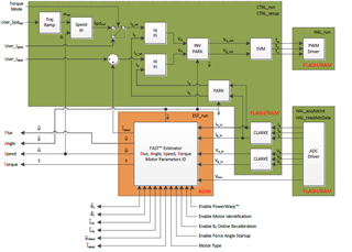
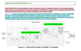
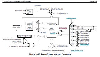
TI SVPWM Module
Input: Alpha / Beta volts divided by DcLinkVoltage to give us Alpha / Beta Duty cycles
Output: A, B, C PWMs scaled from -0.5 to 0.5
TI SVPWM –
There are 3 different SVPWM modules. I’ve tried 2 of the 3. My next step is to try the third one once I get back from vacation but I’m hoping someone here might suggest something they see with the SVPWM modules I am using and something I am misunderstanding.
Current SVPWM module I am using is actually an old one they have. They suggest not using it and using the new one. I am using it because it calculates SVM sectors whereas the other 2 do not and we need the sectors for current phase reconstruction.
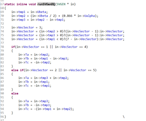
This looks to output a PWM from -0.5 to 0.5 and then I set it to the motor PWM counter compare value.
Issues with this – I compared data at 100 RPM and 500 RPM between WORKING SYSTEM and TI to see how they compare. My takeaways from this on the key differences between WORKING SYSTEM and TI are this –
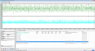
- Q current is the same between the 2 which makes sense since that is where torque comes from
- Tons of D current with TI – causes tons of D voltage which in turn causes tons of motor voltage
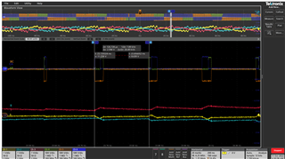
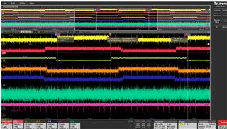
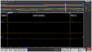
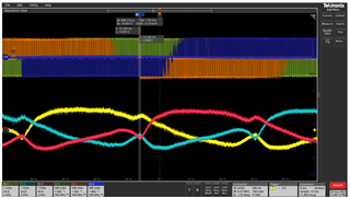
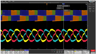
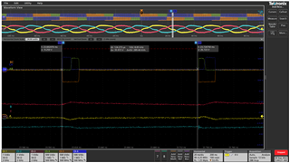
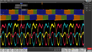
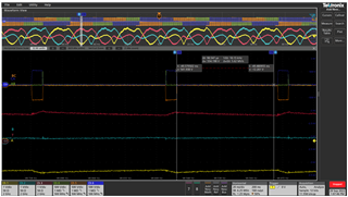
- Duty cycle is obviously different at 500 RPM 60Nm on the scope trace – makes me think SVPWM is wrong – either I don’t understand the output of it or the input of it or the algorithm is wrong.
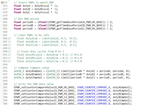
- Why do I need to divide period which is already divided by 2 by 2 again meaning I divide it by 4? The examples do this as well. This confuses me.
- Why does example do (period * duty) + period? Duty is -0.5 to 0.5. This confuses me. The newer SVPWM allows us to scale duty from 0.0 to 1.0 and then just multiply it by the period which makes more sense to me.
Read below the data because I show TI’s newer SVPWM options there.
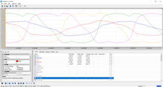
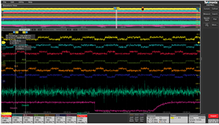
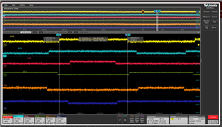
100 RPM 60Nm
WORKING SYSTEM
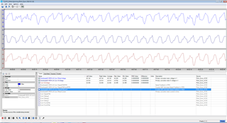
Scope traces

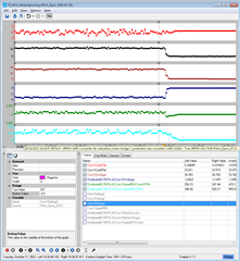
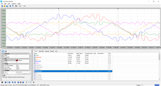
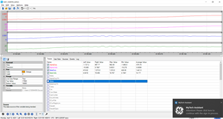
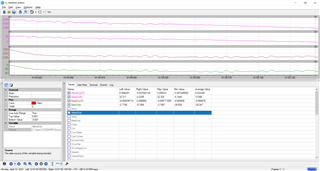
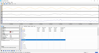
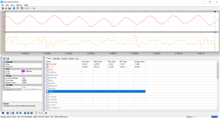
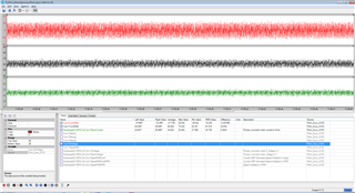
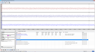
Trends with 10ms sampling – just good for average comparisons
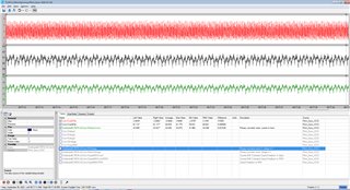
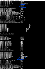
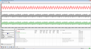
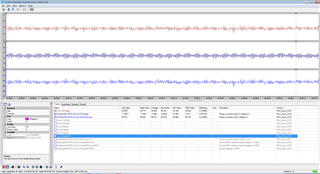
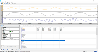
Capture buffers with 250us sampling – good for seeing what is really happening

Duty cycles : -32767 (-1) to 32768 (1)
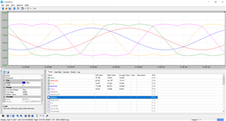
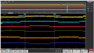
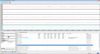
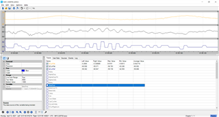
TI

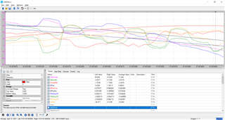
Trends –
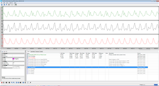
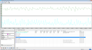


Capture buffers
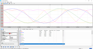
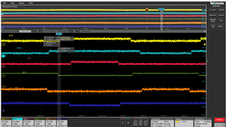
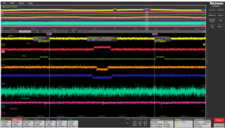
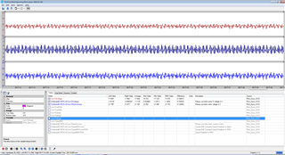
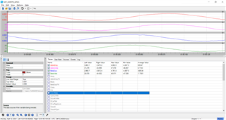
500 RPM 60Nm
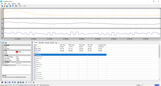
WORKING SYSTEM
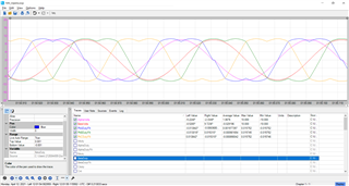
Scope captures
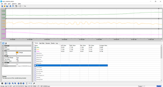
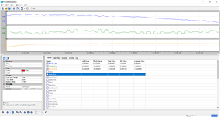
Trends:
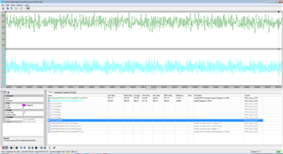
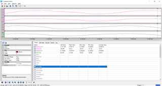
Capture buffers
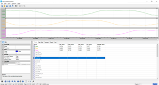
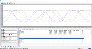
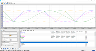
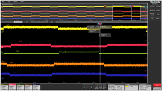
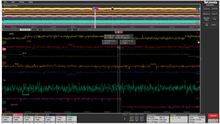
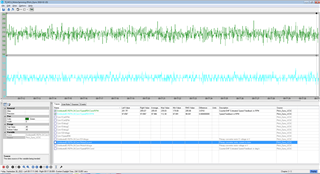
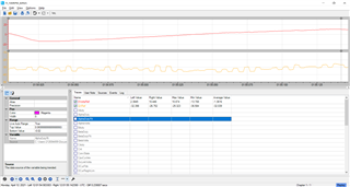
TI
Trends
Capture buffers


TI new SVPWM option 1 –
SVGEN_run
Input – Alpha / Beta (the function will divide them by DcLink voltage to get duty cycles)
Output – A, B, C duty cycles from -0.5 to 0.5
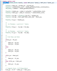
Here I am not sure of 2 things –
- How can they do SVPWM successfully without calculating the sector? How do they tell which IGBTs to turn on?
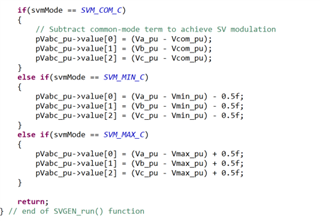
- Which SVM mode are we? I tried SVM_COM_C and that resulted in the same as the older SVGEN that calculates sectors I am trying now.
TI new SVPWM option 2 –
There is a second option that combines the SVGEN_run with SVGEN_current which then does the current reconstruction for us which seems like they must be calculating sectors to be able to do that but not really calling them sectors and saving the sectors.
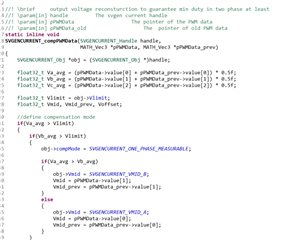
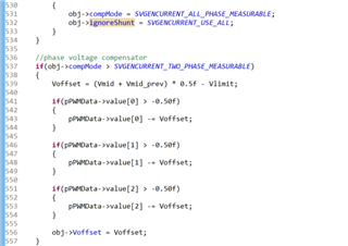
To use it you run, SVGEN_RunRegenCurrent to calculate which phase to reconstruct, then run SVGEN_run above and then call SVGENCURRENT_compPWMData() below it. I have not tried doing this – it might do what we want but it looks like it accounts for phase reconstruction. Here you do not need to divide PWM period already divided by 2 by 2 again and you just multiply the period by duty cycle like I do the other EPWMs which makes sense to me. I like that.
SVGEN_RunRegenCurrent looks a lot like our current reconstruction using SVM sectors to reconstruct the current but it allows for reconstructing 2 of 3 phases.
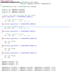
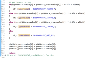
Then after calculating PWMs, you decide which shunt to ignore which seems a lot like deciding which SVM sector you are in:


Therefore, my next step is to try to use this method and see how it performs.
Thanks for your help and sorry for the long post! Hopefully the data and my sharing this helps get to the root cause of the problem and a good next step to try!