Part Number: TMS320F28335
Other Parts Discussed in Thread: TPS3307
Hi Team,
There's an issue from the customer need your help:
1.TMS320F28335 sometimes do not start working after power up, we take it as XINTF bug by now, handling WDT flag and WDT reset.
2.This program have been in use for many years and is used on multiple devices.
3.This has recently been observed on individual devices.
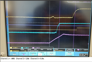
4.Tests have found that the watchdog reset signal is not present when not in operation and the program runs to the XINTF access and fails. Normally, there will be a watchdog reset signal of about 20us around 8ms after the reset signal is pulled high.
From the latest errata sheet of 28335, a sentence has been added for watchdog reset, “Note that the code should sample the WDFLAG bit only after a delay of 8192 SYSCLKOUT cycles from the time reset is deasserted.”
The actual test is currently 8 ms and should meet this.
I wonder is this bug not 100% successful to modify XINTF using watchdog reset? Or is there some issues with the CPU?
Could you help check this case?
Thanks and Regards,
Ben