
- Ask a related questionWhat is a related question?A related question is a question created from another question. When the related question is created, it will be automatically linked to the original question.

Hi Team,
Here's an issue from the customer may need your help:
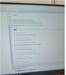
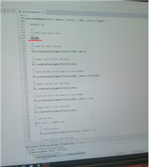
We want that TI DSP to communicate with A3 MCU through SPI interface. However, it was found that the function of enabling pin STE to automatically set high and set low could not be realized through DSP configuration. The DEMO source provided by FAE is also implemented through IO port simulation. As shown in the figures below, SPI read/write enable signal STE is also realized through IO simulation.
--
Thanks & Regards
Yale Li


