This thread has been locked.

If you have a related question, please click the "Ask a related question" button in the top right corner. The newly created question will be automatically linked to this question.

TMS320F28335: Query about IQmath.h for F28335

Part Number: TMS320F28335
Other Parts Discussed in Thread: C2000WARE, CONTROLSUITE

Hi Team,

Our customer has a couple of questions concerning the IQMath library for C2000:

1. What is the meaning of the following line: (_iq)AdcRegs.ADCRESULT0
Is (_iq) used to typecast the content of Adcresult0 register and convert it into global-IQ format?

2. In one of the sample codes the ADC data is being read like this: _IQ16toIQ((_iq)AdcRegs.ADCRESULT0));
The ADCResult0 is getting converted from IQ16 to global IQ format. In floating point sample codes either the ADC result is right shifted 4 places or the result is picked from the ADCMirror register which already contains the right by 4 places data. Why is the ADCResult register content not being shifted to the right 4 times in the above line? Can you explain the working of the above line?
Instead, can either of the following two syntaxes be used:
_IQ12toIQ((_iq)AdcMirror.ADCRESULT0));
_IQ12toIQ((_iq)AdcRegs.ADCRESULT0>>4));
Are the three syntaxes different from each other? Which one is better?

3. In the same sample code there were these two lines as well:
sub = _IQ(1.5);
 _IQmpy(AdcFsVoltage, _IQ16toIQ( (_iq)AdcRegs.ADCRESULT0) )-(sub);
As per these two instructions 1.5 is getting subtracted from the content of ADCRESULT0 to get a bipolar output (eg: AC voltage or AC current). Am I correct in this assumption?
In floating point I have used the Y = MX + C approach (and calculated the value of m and c) to relate the actual value of the signal with the result of the ADCRESULT0 register. Do I still need to use offset = _IQ(1.5) in my case? Or can I use my own offset value that I obtained from my calibration process?

4. I am working on an inverter. After the entire control has been executed and the value of modulation index has been obtained, should I convert the modulation index from IQ format to floating point and then assign to CMPA or CMPB of any of the 6 epwm registers?

5. How may I execute the "if statement" in IQ format?

6. Do I define the global-Q value in my code or should I change it in the IQmath.h header file?

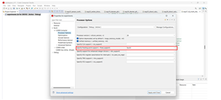
7. Do I need FPU32 library support or softlib in the "specify floating point support" option in the below screenshot? Or should I keep FPU32 library support and include IQmath.h in the code?


Pardon for the long list of questions but hope you can help us. Thanks in advance!


Kind Regards,

Jejomar


  • Dear Jejomar,

    Thanks a lot for posting these questions on my behalf.

    With Regards,

    Ankit

    Research Student

    VIT, Vellore, India

  • Hello,

    Can you please provide the sample code or tell me where it is located in C2000Ware so that I can have context to these questions?

    Best regards,

    Omer Amir

  • Dear Omer Amir,

    Thank you for helping me out. Allow me to provide you the information you seek.

    Firstly

    Line 1: (_iq)AdcRegs.ADCRESULT0

    Line 2: _IQ16toIQ((_iq)AdcRegs.ADCRESULT0));

    Line 3: sub = _IQ(1.5); (Note: line 3 is actually written as #define sub _IQ(1.5);)

    Line 4: _IQmpy(AdcFsVoltage, _IQ16toIQ( (_iq)AdcRegs.ADCRESULT0) )-(sub);

    Note1 : Line 3 is actually written as #define sub _IQ(1.5);

    Note 2: Line 1 is a subset of line 2 and lines 1 and 2 are subsets of line 4

    Lines 1, 2, 3 and 4 are available in the code posted by a user named Anmol D on the following link:

    https://e2e.ti.com/support/microcontrollers/c2000-microcontrollers-group/c2000/f/c2000-microcontrollers-forum/705771/tms320f28335-issue-regarding-three_phase_srf_pll-parameters-in-tms320f28335

    This person posted his query back in 2018 and he has used an internal PLL file titled “SPLL_3ph_SRF_IQ.c” available in the source folder of IQ math based solar library. I do not know which version of CCS did he use back then and so I cannot confirm. I have v1.0, v1.1, and v1.2 versions of solar library in my control suite. The path is as follows:

    C:\ti\controlSUITE\libs\app_libs\solar\v1.2\IQ\source (for v1.2)

    The code available for "SPLL_3ph_SRF_IQ.c" in v1.2 does not match with what is available on the above URL. There could be a chance that the user has added a few extra lines to the original code as per his requirement and thus you may not be willing to look into a consumer’s code.

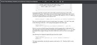
    However, I have found a similar kind of declaration (offset is 1.65 this time) on page 179 of a PDF. This PDF is about a piccolo workshop that may have happened in the past. I am not permitted to upload any kind of files (except for codes) because of the E2E policy. I would request Mr. Jejomar to upload the PDF and screenshot of page 179 of the aforementioned PDF.

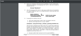
    Yet another similar declaration (however without any offset) is written on page 26 in the PDF version of module 17. This time the PDF is about a TMDSPREX28335 workshop conducted by Frank Bormann. I will attach the code provided by Mr. Bormann below (kindly refer line 186) and I will ask Mr. Jejomar to post this second screenshot and second PDF as well.

    //
    //      Lab17: TMS320F28335
    //      (c) Frank Bormann
    //
    //###########################################################################
    //
    // FILE:	Lab17.c
    // 
    // TITLE:	DSP28335ControlCARD; ePWM1A 2KHz output
    //			25% pulse width active high
    //			low - pass filtered by function "IQssfir" (IQ-Math function)
    //			solution file for Lab17
    //###########################################################################
    //  Ver | dd mmm yyyy | Who  | Description of changes
    // =====|=============|======|===============================================
    //  3.0 | 12 Oct 2009 | F.B. | Lab17 for F28335; 
    //  3.1 | 29 Nov 2009 | F.B  | Lab16 for F28335 @30MHz and PE revision 5
    //###########################################################################
    #include "DSP2833x_Device.h"
    #include "IQmathLib.h"
    
    #define AdcBufLen 50
    #define AdcFsVoltage	_IQ(3.0)		// ADC full scale voltage
    
    // external function prototypes
    extern void InitSysCtrl(void);
    extern void InitPieCtrl(void);
    extern void InitPieVectTable(void);
    extern void InitCpuTimers(void);
    extern void InitAdc(void);
    extern void ConfigCpuTimer(struct CPUTIMER_VARS *, float, float);
    extern  _iq IQssfir(_iq*, _iq*, Uint16);  
    
    
    // Prototype statements for functions found within this file.
    void Gpio_select(void);
    void Setup_ePWM1A(void);
    interrupt void cpu_timer0_isr(void);
    interrupt void adc_isr(void);
    void Setup_ADC(void);
    
    // global variables
    _iq AdcBuf[AdcBufLen];					// ADC results buffer
    _iq AdcBufFiltered[AdcBufLen];			// filtered ADC results buffer
    _iq xBuffer[5] = {0,0,0,0,0};			// filter sample buffer
    // filter coefficients
    _iq coeffs[5] = {_IQ(0.0357), _IQ(0.2411), _IQ(0.4465), _IQ(0.2411), _IQ(0.0357)};
    
    //###########################################################################
    //						main code									
    //###########################################################################
    void main(void)
    {
    	int counter=0;	// binary counter for digital output
    
    	InitSysCtrl();	// Basic Core Init from DSP2833x_SysCtrl.c
    
    	EALLOW;
       	SysCtrlRegs.WDCR= 0x00AF;	// Re-enable the watchdog 
       	EDIS;			// 0x00AF  to NOT disable the Watchdog, Prescaler = 64
    
    	DINT;				// Disable all interrupts
    	
    	Gpio_select();		// GPIO9, GPIO11, GPIO34 and GPIO49 as output
    						// to 4 LEDs at Peripheral Explorer	
    
    	Setup_ePWM1A();		// init of ePWM1A
    
    	Setup_ADC();		// initialize ADC channel A2
    
    	InitPieCtrl();		// basic setup of PIE table; from DSP2833x_PieCtrl.c
    	
    	InitPieVectTable();	// default ISR's in PIE
    
    	EALLOW;
    	PieVectTable.TINT0 = &cpu_timer0_isr;
    	PieVectTable.ADCINT = &adc_isr;
    	EDIS;
    
    	InitCpuTimers();	// basic setup CPU Timer0, 1 and 2
    
    	ConfigCpuTimer(&CpuTimer0,150,20);	// 50 kHz sample period
    
    	PieCtrlRegs.PIEIER1.bit.INTx7 = 1;	// CPU -Timer 0
    	PieCtrlRegs.PIEIER1.bit.INTx6 = 1;	// ADC
    
    	IER |=1;
    
    	EINT;
    	ERTM;
    
    	CpuTimer0Regs.TCR.bit.TSS = 0;	// start timer0
    
    	while(1)
    	{    
    	  		while(CpuTimer0.InterruptCount < 5000);
    			CpuTimer0.InterruptCount = 0;
    			
    			EALLOW;
    			SysCtrlRegs.WDKEY = 0x55;	// service WD #1
    			EDIS;
    
    	  		counter++;
    			if(counter&1) GpioDataRegs.GPASET.bit.GPIO9 = 1;
    				else GpioDataRegs.GPACLEAR.bit.GPIO9 = 1;
    			if(counter&2) GpioDataRegs.GPASET.bit.GPIO11 = 1;
    				else GpioDataRegs.GPACLEAR.bit.GPIO11 = 1;
    			if(counter&4) GpioDataRegs.GPBSET.bit.GPIO34 = 1;
    				else GpioDataRegs.GPBCLEAR.bit.GPIO34 = 1;
    			if(counter&8) GpioDataRegs.GPBSET.bit.GPIO49 = 1;
    				else GpioDataRegs.GPBCLEAR.bit.GPIO49 = 1;
    	}
    } 
    
    void Gpio_select(void)
    {
    	EALLOW;
    	GpioCtrlRegs.GPAMUX1.all = 0;		// GPIO15 ... GPIO0 = General Puropse I/O
    	GpioCtrlRegs.GPAMUX1.bit.GPIO0 = 1;	// ePWM1A active
    
    	GpioCtrlRegs.GPAMUX2.all = 0;		// GPIO31 ... GPIO16 = General Purpose I/O
    	GpioCtrlRegs.GPBMUX1.all = 0;		// GPIO47 ... GPIO32 = General Purpose I/O
    	GpioCtrlRegs.GPBMUX2.all = 0;		// GPIO63 ... GPIO48 = General Purpose I/O
    	GpioCtrlRegs.GPCMUX1.all = 0;		// GPIO79 ... GPIO64 = General Purpose I/O
    	GpioCtrlRegs.GPCMUX2.all = 0;		// GPIO87 ... GPIO80 = General Purpose I/O
    	 
    	GpioCtrlRegs.GPADIR.all = 0;
    	GpioCtrlRegs.GPADIR.bit.GPIO9 = 1;	// peripheral explorer: LED LD1 at GPIO9
    	GpioCtrlRegs.GPADIR.bit.GPIO11 = 1;	// peripheral explorer: LED LD2 at GPIO11
    
    	GpioCtrlRegs.GPBDIR.all = 0;		// GPIO63-32 as inputs
    	GpioCtrlRegs.GPBDIR.bit.GPIO34 = 1;	// peripheral explorer: LED LD3 at GPIO34
    	GpioCtrlRegs.GPBDIR.bit.GPIO49 = 1; // peripheral explorer: LED LD4 at GPIO49
    	
    	GpioCtrlRegs.GPCDIR.all = 0;		// GPIO87-64 as inputs
    	EDIS;
    }  
    
    void Setup_ePWM1A(void)
    {
    	EPwm1Regs.TBCTL.bit.CLKDIV =  0;	// CLKDIV = 1		
    	EPwm1Regs.TBCTL.bit.HSPCLKDIV = 0;	// HSPCLKDIV = 1
    	EPwm1Regs.TBCTL.bit.CTRMODE = 2;	// up - down mode
    
    	EPwm1Regs.AQCTLA.all = 0x0060;		// set ePWM1A on CMPA up
    										// clear ePWM1A on CMPA down
    
    	EPwm1Regs.TBPRD = 37500;			// 2KHz - PWM signal
    	// TBPRD = fCPU / ( 2 * fPWM *CLKDIV * HSPCLKDIV)
    	// TBPRD = 150MHz / (2 * 2kHz * 1 *1)
    	// TBPRD = 37500
    	EPwm1Regs.CMPA.half.CMPA  = 28125;	// 25% duty cycle
    	// CMPA = (100% - duty cycle)*TBPRD
    	// CMPA = 0.75 * 37500 = 28125
    } 
    
    interrupt void cpu_timer0_isr(void)
    {
    	CpuTimer0.InterruptCount++;
    	AdcRegs.ADCTRL2.bit.SOC_SEQ1 = 1;	// start ADC by software
    	EALLOW;
    	SysCtrlRegs.WDKEY = 0xAA;	// service WD #2
    	EDIS;
    	
    	PieCtrlRegs.PIEACK.all = PIEACK_GROUP1;
    }
    
    void Setup_ADC(void)
    {
    	InitAdc();
    	// Configure ADC
       	AdcRegs.ADCTRL1.bit.SEQ_CASC = 1;	   // Cascaded Sequencer Mode
       	AdcRegs.ADCTRL1.bit.CONT_RUN = 0;	   // No Continuous run
       	AdcRegs.ADCTRL1.bit.CPS = 0;		   // prescaler = 1	
       	AdcRegs.ADCTRL2.bit.EPWM_SOCA_SEQ1 = 0;  // Disable EPWM_SOCA to start SEQ1
    	AdcRegs.ADCTRL2.bit.INT_ENA_SEQ1 = 1;  // Enable SEQ1 interrupt
    	AdcRegs.ADCTRL2.bit.INT_MOD_SEQ1 = 0;  // with every EOS
    	AdcRegs.ADCTRL3.bit.ADCCLKPS = 3;	   // Divide HSPCLK by 6
    	AdcRegs.ADCMAXCONV.all = 0;		       // 1 Conversion per start  
        AdcRegs.ADCCHSELSEQ1.bit.CONV00 = 2;   // Setup ADCINA2 as input channel.
    }
    
    interrupt void adc_isr(void)
    {
    	static Uint16 index=0;                     	    // index into ADC buffers
    	AdcBuf[index] = _IQmpy(AdcFsVoltage, _IQ16toIQ((_iq)AdcRegs.ADCRESULT0));
    	
    	/*** Call the filter function ***/
    	xBuffer[0] = AdcBuf[index];				// Add the new entry to the delay chain
    	AdcBufFiltered[index] = IQssfir(xBuffer, coeffs, 5);
    
    	index++;									// Increment the index
    	if(index == AdcBufLen) index = 0;			// Rewind the pointer to beginning
    	// Reinitialize for next ADC sequence
      	AdcRegs.ADCTRL2.bit.RST_SEQ1 = 1;   	// Reset SEQ1
      	AdcRegs.ADCST.bit.INT_SEQ1_CLR = 1;		// Clear INT SEQ1 bit
      	PieCtrlRegs.PIEACK.all = 1;   			// Acknowledge interrupt to PIE
    }
    //===========================================================================
    // End of SourceCode.
    //===========================================================================
    

    Once you have both the screenshots and both the PDFs then could you answer to my questions please? I am hoping that my queries are trivial and not complex to extend this thread.

    Waiting for a solution.

    With Regards,

    Ankit

    Research Student

    VIT, Vellore, India

  • Hi Omer,

    For some reason Ankit, our customer was unable to upload the files in subject so I'll be uploading the files on his behalf.


    Piccolo workshop PDF.pdf


    Module 17 TMDSPREX28335 workshop PDF by Frank Bormann.pdf


    Kind Regards,

    Jejomar

  • Hello Jejomar,

    Before I go in depth answering the questions, I want to explain some things out of order. For question 7, the F28335 has the FPU integrated on it, meaning that you can use floating-point operations instead of fixed-point math (such as in IQmath). In the case where the customer is using a system that already uses IQmath or the project requires them to use IQmath, then they can use that instead. Floating-point operations when enabling the support are optimized with the FPU. For the specified device, you can only use FPU32 for the --float_support processor option (only the F2838x device has FPU64 support).

    (Questions 1-3) If the customer require using IQmath, then I can explain how the format works. The N in IQN dictates the level of precision of the fixed-point number, or how many bits in a 32-bit integer are reserved for the fractional portion of the number (i.e. for IQ30 there are 30 bits reserved for the fractional portion and 2 for the integer portion, making the range of values -2 to 1.999 999 999). This can be seen in the IQmath_Quickstart.pdf located in C2000Ware (C2000Ware_4_XX_XX_XX\libraries\math\IQmath\c28\docs). Where some of the integers are cast to an _iq datatype, this would basically be telling the compiler to treat some portion of that number as integer and the rest as fractional for IQmath. Typically if you're casting an integer to fixed-point format you want to shift the bits left to account for the additional fraction part of the number, I'm not sure why it's not done in the code you attached.

    If the customer has questions regarding another user's code, they are better off asking that user. Unless it is an example that is part of TI, there may be a lot of guesswork involved when trying to determine the logic behind another customer's code. I will try to see if we have an expert who can answer the other questions not related to IQmath/FPU.

    For question 5, if the two IQ numbers being compared are of the same IQN format, they can be compared like any other integer since they are fixed-point. If there are any issues, let me know and I can try testing on my side.

    For question 6, you need to modify the global-Q value in the actual header file, there is no way to modify it via a function or creating your own macro without overwriting this header file anyways.

    I am not an expert in the area for question 4, so I will try to find someone else to answer it.

    Best regards,

    Omer Amir

  • Dear Jejomar and Omer,

    Jejomar, thank you very much for uploading the screenshots and the PDFs on my behalf.

    I appreciate your honesty and etiquettes when you admitted that you are not from the field related to question 4. Thank you very much for the clarification on the remaining 6 queries.

    I admit that the URL provided by me in my previous reply contained a code that may have been modified by that user which made the code out of scope to be looked into. However, Mr. Jejomar did provide two different screenshots containing similar lines that belong to TI. Perhaps those PDFs, screenshots and the code (coded by TI engineers) that I attached could have been referred. Anyways, I applied some reasoning and logic of own and I was able to find exact answers to all the questions.

    Ans 1: (_iq)AdcRegs.ADCRESULT0 does indeed typecast the content of AdcRegs.ADCRESULT0 register to IQ format (even though there is no actual datatype like IQ).

    Ans 2: Both AdcRegs.ADCRESULT0 and AdcMirror.ADCRESULT0 are 16 bit registers, while the ADC result is only 12 bits.  0th to 3rd bits are inaccessible in case of AdcRegs.ADCRESULT0 register(because it is left justified), and 12th to 15th bits are inaccessible in case of AdcMirror.ADCRESULT0 (because it is left justified). So even if the code includes _IQ16toIQ((_iq)AdcRegs.ADCRESULT0)) or _IQ16toIQ((_iq)AdcMirror.ADCRESULT0)) only the information from the relevant 12 bits of either registers would be extracted. _IQ12toIQ((_iq)AdcMirror.ADCRESULT0)) converts the information to global-Q format directly (because the AdcMirror.ADCRESULT0 contains the data in right justified format by default) while _IQ12toIQ((_iq)AdcRegs.ADCRESULT0>>4)) converts the information to global-Q format after right justifying the content. So essentially all the three styles ( a) _IQ16toIQ((_iq)AdcRegs.ADCRESULT0)), b) _IQ12toIQ((_iq)AdcRegs.ADCRESULT0>>4)), c) _IQ12toIQ((_iq)AdcMirror.ADCRESULT0))) produce exactly the same results. However, because there is no waiting involved with AdcMirror registers I would prefer _IQ12toIQ((_iq)AdcMirror.ADCRESULT0)).

    Ans 3: A user can implement the Y = MX + C approach with his own calibrated M and C values. However, with correct syntax. For example: _IQ(M)*_IQ12toIQ((_iq)AdcMirror.ADCRESULT0)) + _IQ(C);

    Ans 4: After obtaining the modulation index, the user may convert the final result into the datatype of CMPA or CMPB registers (it is unsigned int after checking the watch window).

    Ans 5: The If statement can be executed in the same as it is used with other datatypes.

    Ans 6: One can define the global-Q value in the main code itself with the following syntax:

    #define GLOBAL-Q 22 // default Q is 24

    #include "IQmathlib.h"

    Just define Global-Q before including IQmath.h in the code

    Ans 7: User can keep FPU32 in the “specify floating point support” and include IQmath.h in the main code.

    Looking forward to your opinion.

    With Regards,

    Ankit

    Research Student

    VIT, Vellore, India

  • Hello Ankit,

    1. Yes, it is being cast; technically the _iq or IQN is a datatype, but it's really just a long integer that is treated as dictated by the IQmath library.

    2. From what I've found in the reference manual, this is correct

    3. I believe this code comes from the other user, so you can confirm this with them (I could not find this mentioned in the TI workshop included here)

    4. I did not understand your question before, but yes your understanding is correct; make sure that if you're converting the result from the IQ datatype that you shift the bits accordingly to truncate the fractional portion of the integer.

    5. Yes, because it is not floating-point, it is fixed-point

    6. Yes, if you define it before the IQmathlib.h header file then that will work; make sure to use GLOBAL_Q, as this is the actual macro that's used.

    7. You can do this, but I don't understand why you would. IQmath is used in the place of floating-point when an FPU is not available on the device. You have an FPU on the F2833x device, so you could use IQmath and include FPU32 for the floating-point support, but the only reason to keep this would be to convert one to the other in the case where the project is solely based on IQmath (fixed-point math), but you desire using floating-point for higher precision. If this is a case where the project you're working on requires it, that's fine. I just want to make sure you're aware that IQmath is essentially only included for legacy reasons, it is intended that users will use floating-point math for precision math operations since the hardware supports it.

    Best regards,

    Omer Amir

  • Hello Omer,

    Thanks a lot for your approval of my explanation and also for correcting me on my assumption that IQ is not a datatype. As all of my questions have been answered you may go ahead and close this thread.

    Tons of thanks to Jejomar as well for posting the query and the screenshots and PDFs on my behalf.

    With Regards,

    Ankit

    Research Student

    VIT, Vellore, India