This thread has been locked.

If you have a related question, please click the "Ask a related question" button in the top right corner. The newly created question will be automatically linked to this question.

TMS320F2812: DSP TMS320F2812 Program Doesn't Function Properly on First Start-Up

Part Number: TMS320F2812

Hi,

I have a controller board with DSP (Controller) & FPAG (for timing) and I have an problem with the DSP on the first startup.

This Controller had a redesign of FPGA (Spartan 3 of Xilinx replaced by MAX10 of Intel) and What is happening in the first time is that some registers (I don't know who) dose not working and I have Error Communication with the GUI of the machine 

The communication between the DSP and the GUI is I2C.When I checked the Supply Voltage I see there is a different between 2 close start up (attached photos)

First Start-Up:                                                  Second Start-Up:


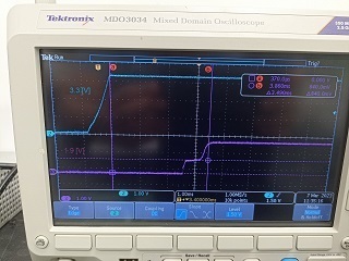
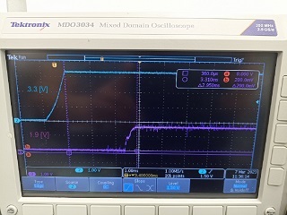
Can you help me understand what could be the cause?


BR,

Dror 

  • Hello Dror,

    It's not clear in the image which signal indicates what, can you please clarify? Also what do you mean by some of the registers do not work on the first startup?

    Best regards,

    Omer Amir

  • Hello Omer,

    What I mean by some registers that do not work is that in the first start-up the communication between DSP and GUI (Computer) dosen't work.

    There are two line that go to the GUI GPIOF4/SCITXDA (Pin 155) & GPIOF5/SCIRXDA (Pin 157) in RS232 protocol.

    What I see in the Scop that the DSP does not send any information (the line is HIGH permanently) and the GUI send information.

    About the photo that I sent, I can't send them in high resolution only 320*240

    BR,

    Dror   


  • Hello Dror,

    I will look into this and try to get back to you by tomorrow.

    Best regards,

    Omer Amir

  • Hello Dror,

    I wanted to clarify what device you're using, I was talking with another expert and there is no I2C module on the F2812 device.

    Are you probing VDD and VDDIO using the scope? If so, can you show me how you are powering up the device and the LDO?

    Best regards,

    Omer Amir

  • Hello Omer,

    I am sorry for the late response I was on vacation.

    1. For I2C communication we use external RS232 component MAX3232ESE+ of Maxim Integrated.

    2. Attached the photo of 3.3V from LDO, VDD & VDDIO

  • I'm sorry the photo did not sent.

  • Hello Dror,

    So are you manually configuring the GPIO pins to perform the I2C protocol, and the issue you're seeing is that the GPIO are not behaving as expected? Or is the voltage on the rails incorrect? Because the I2C module is not on the F281x device, I'm assuming you're manually toggling the pins for the I2C so I'm not sure what you're citing as the problem with the DSP not sending data (the DSP I'm assuming you're referring to is the F281x).

    Best regards,

    Omer Amir

  • Hi Omer,

    Eventually the problem is that the DSP does not execute a boot.

    What could be the reason that the DSP boot only in the second start (the time should be very fast between two start-up, if the second time delay in half a minute the DSP will not boot)

    Best Regards,

    Dror Moshe

  • Dror - Can you provide more information on how the start is initiated?

    is the device in stand-alone operation ? Is each start from a power-on reset? or is code composer studio connected and you perform a debug reset?

    Check that the boot mode pins are in the right configuration and held long enough. The datasheet has the hold time for boot-mode pins. 

    regards

    Lori