This thread has been locked.

If you have a related question, please click the "Ask a related question" button in the top right corner. The newly created question will be automatically linked to this question.

C2000WARE-MOTORCONTROL-SDK: How should I control the minimum duty cycle of the PWM output

Part Number: C2000WARE-MOTORCONTROL-SDK

Hello,

I am trying to run is04_signal_chain_test_eabi from MotorControl SDK Version 4.02.01. So far, I have been able to spin the motor in open loop using is03_signal_chain_test_eabi.

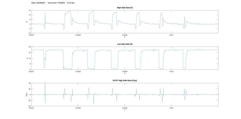
As far as I can presume, the parameters for  voltage and current feedback are correct. The PWM signal is running at 20KHz with a dead time of 2.5µs. The rise DV/DT of the gate voltage is currently about 20 V/µs.

Given all this conditions, when I try to spin the motor using is04_signal_chain_test_eabi, the motor just make a click noise but doesn't start. The IGBT Gate Drive, goes to protection mode and shuts off the gates.

My assumption is that, at the time of failure, the duty cycle of the high side PWM signal is too short and the gate voltage never raises above the minimum switch voltage and the high side IGBT never turns on. The IGBT Gate Driver checks the IGBT's Vce. Because of the fact that Vce doesn't drop after an specified time (Vce should go below 9V after 250ns), the divers detect a short circuit condition and shut down the output.

Could you please give me some insight on what is happening? Is there any mechanism to control the duty cycle of the PWM signal? Is the PI controller already saturating? How can I check if the PI controller is saturating?

For reference, these are the gate voltages. IGBT threshold voltage is 6.5V.

  • Hi,

    I have found this snippet in HAL_writePWMData

            float32_t V_pu = -pPWMData->Vabc_pu.value[pwmCnt];
            float32_t V_sat_pu = MATH_sat(V_pu, 0.5, -0.5);
            float32_t V_sat_dc_pu = V_sat_pu + 0.5;
            int16_t pwmValue  = (int16_t)(V_sat_dc_pu * period);
            ...
            EPWM_setCounterCompareValue(obj->pwmHandle[pwmCnt],
                                        EPWM_COUNTER_COMPARE_A,
                                        pwmValue);

    I can see that the duty cycle has the ability to go all the way from 0% to 100% (V_sat_dc_pu.) Should I close the saturation window here? Although this would reduce the maximum voltage vector and maybe casue some distorsion, this would prevent the duty cycle to go very low. Am I missing something? What other option are there available? It appears that indeed the PI controller is going to saturation.

  • Hi,

    I have found the set point definition for the PI controls. As I am using an induction motor, should I specify a set point different than zero for the Id reference? and how should I calculate this set point to be able to run  is04_signal_chain_test_eabi?

    MATH_Vec2 IdqSet_A = {0.0, 0.75};

  • You may need to set the correct "USER_ADC_FULL_SCALE_CURRENT_A" value in user.h and the sign of "current_sf" in HAL_readADCDataWithOffsets() in hal.h according your own hardware board for running lab04.

    static inline void
    HAL_readADCDataWithOffsets(HAL_Handle handle,HAL_ADCData_t *pADCData)
    {
    HAL_Obj *obj = (HAL_Obj *)handle;

    float32_t value;

    float32_t current_sf = HAL_getCurrentScaleFactor(handle);
    float32_t voltage_sf = HAL_getVoltageScaleFactor(handle);

  • Hello Yamming,

    Thank you for your response.

    I changed to a PM motor. Now, when I run is04_signal_chain_test_eabi, the motor is activated at Zero Speed with Full Torque. The gate driver no longer detects a desaturation of the IGBT.

    I have reviewed what you have suggested. Although, I am using a floating shunt resistor (x3) - Could this be an issue? This is my set-up

    The shunt resistor is in-line with the phase with the positive side of the amplifier connected to the motor side. So I assumed that the sign of "current_sf" should be negative so I changed HAL_readADCDataWithOffsets() in hal.h as shown

    static inline void
    HAL_readADCDataWithOffsets(HAL_Handle handle,HAL_ADCData_t *pADCData)
    {
    HAL_Obj *obj = (HAL_Obj *)handle;
    
    float32_t value;
    
    float32_t current_sf = - HAL_getCurrentScaleFactor(handle);   // I Placed the negative sign here
    float32_t voltage_sf = HAL_getVoltageScaleFactor(handle);

    I also double checked USER_ADC_FULL_SCALE_CURRENT_A and calculated it with the following equation

    Ifs [A] = 3.3 [V] / ( 0.005 [V/A] * Isolator Gain * Differential Gain) = 100.88 [A]

    Where:

       Isolator Gain = 8.2

       Differential Gain =  0.79787

  • I have reviewed what you have suggested. Although, I am using a floating shunt resistor (x3) - Could this be an issue?

    You may try to run the motor with is03 first, and use the datalog, PWMDAC or DAC to verify the current sensing. Make sure the current sensing is correct, and then to run the is04 lab.

  • Hi Yanming, thanks for your support.

    I finally found out what I was doing wrong. As I had not idenfied the motor at the time I was first trying to run  is04_signal_chain_test_eabi, I was not providing values for R and L

    #define USER_MOTOR_Rr_Ohm                 (NULL)
    #define USER_MOTOR_Rs_Ohm                 (NULL)
    #define USER_MOTOR_Ls_d_H                 (NULL)
    #define USER_MOTOR_Ls_q_H                 (NULL) 

    This was causing all Kp_Id, Ki_Id, Kp_Iq and  Ki_Iq to resolve to zero in setupControllers() in labs.h (although it is weird beacuse there's a division by zero, I assume it is due to floating point nuisances.) For this reason, the output of the PI controller was zero at all times.

        float32_t RdoverLd_rps = Rs_d_Ohm / Ls_d_H;    // RdoverLd_rps is resolving to zero
        float32_t RqoverLq_rps = Rs_q_Ohm / Ls_q_H;    // RqoverLq_rps is resolving to zero
        float32_t BWc_rps = userParams.BWc_rps;
        float32_t currentCtrlPeriod_sec =
                    (float32_t)userParams.numCtrlTicksPerCurrentTick /
                    userParams.ctrlFreq_Hz;
        float32_t outMax_V = userParams.Vd_sf * userParams.maxVsMag_V;
    
        float32_t Kp_Id = Ls_d_H * BWc_rps;
        float32_t Ki_Id = RdoverLd_rps * currentCtrlPeriod_sec;
    
        float32_t Kp_Iq = Ls_q_H * BWc_rps;
        float32_t Ki_Iq = RqoverLq_rps * currentCtrlPeriod_sec;
    

    So I went ahead and executed is05_motor_id_eabi. This program calculated R and L and now the motor is running smoothly.

  • Hi Yanming, thanks for your support.

    I finally found out what I was doing wrong. As I had not idenfied the motor at the time I was first trying to run  is04_signal_chain_test_eabi, I was not providing values for R and L

    #define USER_MOTOR_Rr_Ohm                 (NULL)
    #define USER_MOTOR_Rs_Ohm                 (NULL)
    #define USER_MOTOR_Ls_d_H                 (NULL)
    #define USER_MOTOR_Ls_q_H                 (NULL) 

    This was causing all Kp_Id, Ki_Id, Kp_Iq and  Ki_Iq to resolve to zero in setupControllers() in labs.h (although it is weird beacuse there's a division by zero, I assume it is due to floating point nuisances.) For this reason, the output of the PI controller was be zero at all times.

        float32_t RdoverLd_rps = Rs_d_Ohm / Ls_d_H;    // RdoverLd_rps is resolving to zero
        float32_t RqoverLq_rps = Rs_q_Ohm / Ls_q_H;    // RqoverLq_rps is resolving to zero
        float32_t BWc_rps = userParams.BWc_rps;
        float32_t currentCtrlPeriod_sec =
                    (float32_t)userParams.numCtrlTicksPerCurrentTick /
                    userParams.ctrlFreq_Hz;
        float32_t outMax_V = userParams.Vd_sf * userParams.maxVsMag_V;
    
        float32_t Kp_Id = Ls_d_H * BWc_rps;
        float32_t Ki_Id = RdoverLd_rps * currentCtrlPeriod_sec;
    
        float32_t Kp_Iq = Ls_q_H * BWc_rps;
        float32_t Ki_Iq = RqoverLq_rps * currentCtrlPeriod_sec;
    

    So I went ahead and executed is05_motor_id_eabi. This program calculated R and L and now the motor is running smoothly.

  • Good. Please let's know if have any further questions. Thanks!