This thread has been locked.
If you have a related question, please click the "Ask a related question" button in the top right corner. The newly created question will be automatically linked to this question.
Hello,
I am attempting to work through the can_flash_programmer example from the C2000Ware - C:\ti\c2000\C2000Ware_4_03_00_00\utilities\flash_programmers\can_flash_programmer
I was able to successfully convert the firmware and flash kernel from .out files to .dat files using the hex2000 utility and am now trying to complete the second step in the readme file:
Usage of the CAN flash programmer is as follows:
can_flash_programmer.exe -d f28003x -k <kernel hex file name> -a <firmware hex file name>
...
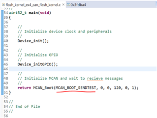
"The F28003x device needs to be set to MCAN Boot before running this command. The CAN flash programmer
will send the kernel file to the F28003x device, pause for a few seconds, and then send over the
application file to program it to flash. The can_flash_programmer can be closed once the application transfer has finished."
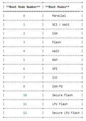
But I'm confused on how to set the device to MCAN Boot. Looking at the Technical Reference Manual, it talks about GPIO pins 24 and 32.
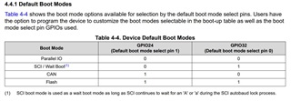
How are these pins related to the emulator bootloader register values (highlighted below)?
What would I need to write to 0xD00 to start the CAN bootloader on a CPU reset?
Any help you can provide will be greatly appreciated.
Thanks!
Emma,
You need to be clear on which boot-mode you are using:
CAN boot-mode is facilitated by the DCAN module. This mode can be selected by GPIO24 & GPIO32.
CAN FD boot-mode is facilitated by the MCAN module. This mode cannot be selected by GPIO24 & GPIO32.
What would I need to write to 0xD00 to start the CAN bootloader on a CPU reset?
0xD00 is just a RAM location that you can write to through CCS.
Thank you for the response. It looks like the example in the TI SDK utilizes MCAN
- C:\ti\c2000\C2000Ware_4_03_00_00\utilities\flash_programmers\can_flash_programmer
I am launching the C:\ti\c2000\C2000Ware_4_03_00_00\driverlib\f28003x\examples\flash.
From there it states in the can_flash_programmer readme.txt file to do the following: The F28003x device needs to be set to MCAN Boot before running this command.
So, if it is using MCAN and I cannot set GPIO24 and GPIO32 what GPIO pins do I need to use? I found the following in the datasheet:
If GPIO4 and GPIO5 are the correct pins, how do I set them? Do I need to write them directly in the kernel or through CCS somehow? Or some other way?
I asked about 0xD00 because in other processors this is a location for an EMU_BOOTCTRL register where you can set the bootmode while developing.
Thank you for the response. It looks like the example in the TI SDK utilizes MCAN
Understand, but what is the mode you want to use? Does your application need the higher-bit-rate and payload size offered by MCAN or does the lower bit-rate/payload of DCAN would suffice?
If GPIO4 and GPIO5 are the correct pins, how do I set them?
You are mixing up the boot-mode select pins with pins used for the peripheral function. What Table 4-41 shows you is which GPIO pins are used for the MCAN function. This is after you have selected the MCAN boot mode.
Hi Emma,
> So, if it is using MCAN and I cannot set GPIO24 and GPIO32 what GPIO pins do I need to use?
These pins are connected to the S3 boot mode switch on the device.
> If GPIO4 and GPIO5 are the correct pins, how do I set them?
GPIO4 and GPIO5 are set through the boot mode chosen in MCAN flash kernel example project.
> Do I need to write them directly in the kernel or through CCS somehow?
Using emulation boot mode, you can write them through CCS by setting the following memory locations for MCAN boot mode:
0xD00 - 0xFFFF
0xD01 - 0x5AFF
0xD04 - 0x0068 (Sendtest Boot Mode)
This Sendtest Boot Mode tells the device to use GPIO4 and GPIO5 for the MCAN.
Then reset the device CPU and press resume in CCS. It is now ready to accept the transfer from the host programmer to the device.
Thanks and regards,
Charles
Hi Charles,
There are two different set of GPIOs pairs.
- GPIO24 and GPIO32 is used for selecting which boot mode is to be used by the controller to load the program
- GPIO4 and GPIO5 are the CANTx and CANRx respectively required for the CAN communication.
I hope this solves the confusion with the GPIO pairs here in the example and implementation.
Thanks,
Ronak
Hi Ronak,
Thanks for clarification. Again, do note that in the CCS we will need to set the D0 emulation/bootpin-config registers to enter MCAN boot mode. Our main concern for boot pins TX/RX are the ones associated with MCAN mode that are set by the flash kernel example.
Regards,
Charles
Thanks everyone,
Here are the steps I am following to try and get the CAN flash programmer working:
1. I have a project loaded on the processor. In CC I set the emulation registers to the previously recommended values
2. I clicked on the CPU Reset button and select resume
3. On the PC side in a command line window, I type the command given in the readme file.
I'm using the PCAN-USB Pro FD which is also plugged into my computer and connected to the CAN HI, LO, and GND pins on the launchpad. The PEAK device USB light is blinking green, indicating a solid connection to the computer, and the CAN1 channel light is also blinking green indicating a software application is connected to the CAN interface, but there doesn't seem to be any data moving through (expecting the green LED to blink faster during a transfer of data), and the LED on the microcontroller isn't blinking meaning the LED application was not programmed to FLASH.
If I pause CC after sending the command on the PC side. I see the following (I was trying to access the function call tree):
It says that no symbols are defined. Could that be an issue?
.
Any ideas on how to debug this moving forward or what I may be doing wrong?
Thanks for the help!
-Emma
Hi Emma,
A few things to check:
1. Are the Flash kernel text file and the led application file in the same location as the host programmer executable?
2. Is the Flash kernel project and led projects set to use the LAUNCHXL-F280039C settings if using the launchpad? This must be provided as a part of the symbols for the project, as shown below. Without this being set, the LED will not be visible after download.
3. Is the CAN routing switch on the device set low? This will allow the transfer to occur to GPIO Lo/Hi instead of the Booster pack heading.
Pausing the CC to see that no symbols are loaded indicates that the kernel was not downloaded.
Once the MCAN Flash kernel and application have downloaded to the device, the device boot mode can be set to Flash through the S3 boot switch.
Posting an image of my setup as well.
Thanks and regards,
Charles
Emma,
On a slightly different note, Table 4-5. Custom Boot Modes on page 550 is missing some rows. Below is the complete table:
Emma,
Glad to hear you were able to get it running by pulling down the CAN Route switch for the device.
Thanks and regards,
Charles