Hi I am continuing with my last post because I can not see the reply option there. I was absent for some reason for some days, couldn't reply the last thread and it was locked now. So here I am attaching the last thread to continue.


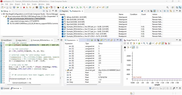
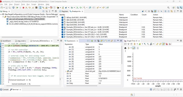
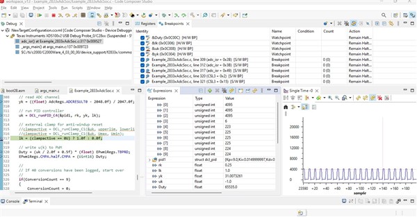
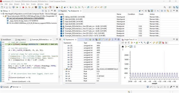
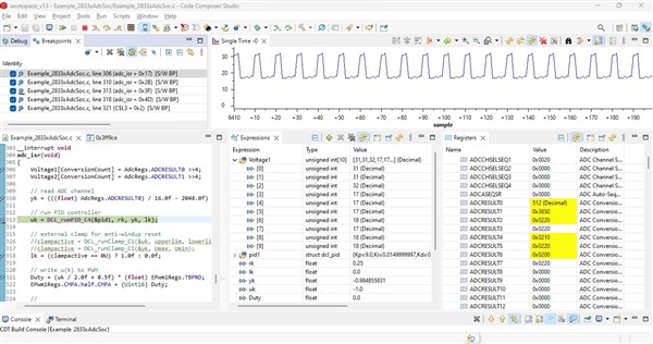
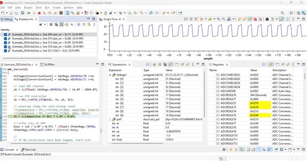
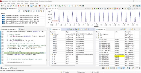
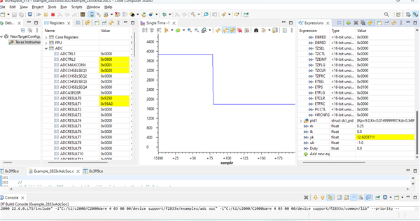
My concern was that yk is well outside of the range of +/-1, it was showing 12.9f on IMAGE 5 and it shouldn't be the case. If we do a quick calculation, P-path's control effort would be abs(yk - rk) * Kp = (12.9 - 0.25) * 9 = 113.85, which would be clamped to 1.
Question 1:
Here I see yk at 0V is 0 but yk at 1.2V is 12.9. it must clamped to +/-1 for ADC value 0 at 0V and 4095 at 3V over extreme values as shown in pictures. The previous replies explain that the controller at kp =9 is overreacting and showing the maximum control effort . I want to confirm that, should I set the Kp or other control parameters to make the yk = +/-1 ? If you check in DCL guide example 3,4 &5. rk can be change, uk could be change yk must be in between -1 & +1. What changes should I do to keep it between +1 and -1 ?
Currently, do you have any feedback mechanism that allows you to use the duty cycle and influence your adc input? If there isn't any feedback, PID controller will never be able to reach the target voltage and its I-path would eventually saturate the feedback. And if you don't have a consistent input influence, the controller would eventually settle at 0% as it reaches the target value. The only way for a controller to constantly provide a control effort is if you have an constantly applied influence to begin with.
Question 2:
I am implementing this circuit which is shown in the picture below. Input Vin is 20V DC and output Vout is 10V constant DC in the Buck converter physical plant model. But here I am separating the above plant model for my test from the feedback part and then providing a 0-3V DC output from the external power supply. The feedback part will generate an ePWM signal having duty cycles for the gate transistor (Gate Driver). As I said before that I am removing the above Buck plant model and then will check this changing duty cycle signals through oscilloscope based of my 0-3V DC supply. Here I can change my supply values for output like 0V, 1V, 1.5V, 2V etc and will see the effect duty cycles accordingly. Is it necessary now to connect plant model with Feedback part for my initial setup having PID mechanism? will the PID be able to reach the target value(Vref value) at this setup having no Plant model but only using external power supply 0-3V and then check the simulation on hardware ?

If you just need proportional duty cycles based on ADC readings, you don't need a PID to achieve that, directly assigning ADC reading to the duty cycle register would suffice, provided no external influence to the system.
Question 3:
For this condition, I need to make formula/relation between ADC vs duty cycle where ADC has two extreme values 0 (0V) and 4095(3V) and the duty cycle 0 and 100% respectively. If any such value achieves like 1.2V or 1638 digital value then duty cycle would roughly be around 45% or 40% in between. This formula could be implemented in my code but the problem is that there will be no clamping/saturation or anti windup reset setup in case of your output goes high at the startup of Buck Converter Plant model and you need to settle at one value. This was the reason that I am using PID which can control the output and settle at one value with respect to reference/set value Vref.
uk/2.0f + 0.5f was an attempt to normalize the control output range from -1.0~1.0f to 0~1.0f, representing 0% to 100% of the duty cycle.
Question 4:
What does ~ means? Does it means -1 to +1? and how it equals to 0 ~ 1? As i know this formula yk = ((float) AdcRegs.ADCRESULT0 - 2048.0f) / 2047.0f; it gives yk values between -1 to +1? so how it can equal to 0 ~ 1?
Question 5
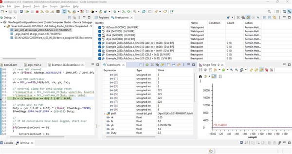
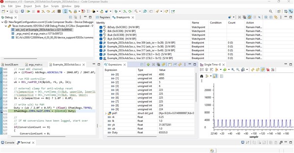
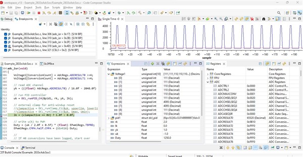
I am attaching a code here. With this program, there will be no middle value in duty cycle I can get as you said before either you will have 0% duty or 100% duty cycle using PID controller. One thing i noticed in DCL guide example 3,4,& 5. lk is always 1.0 not 0. But in my case it remains 0 all the time. why?
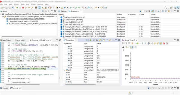
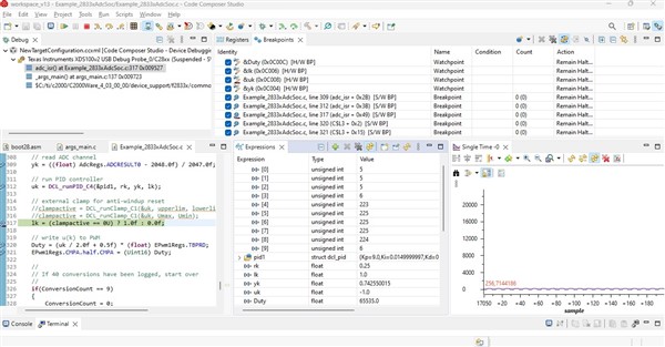
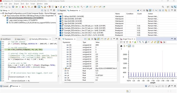
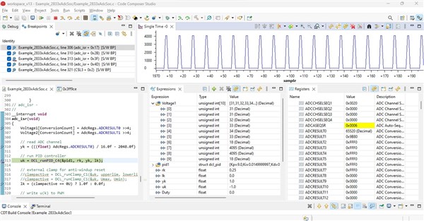
At 0V, Duty is 65535.0
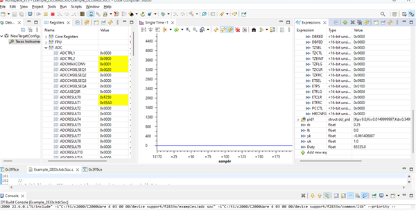
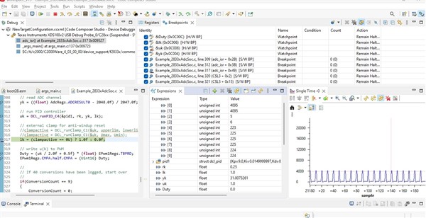
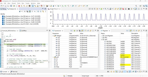
At 3V, Duty is 0
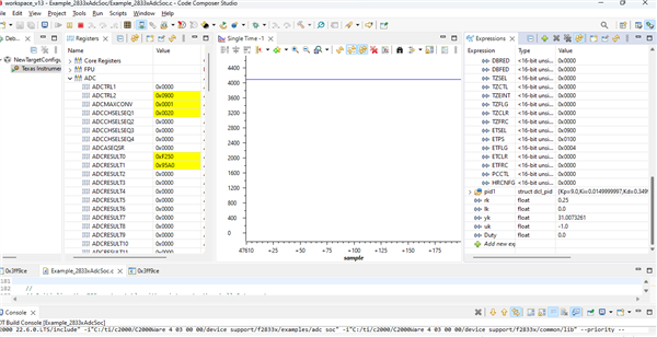
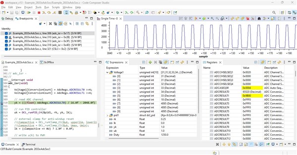
At 1.2V, Duty is 0.
Please suggest the answers for above questions accordingly.
Thanks
Regards
Arsalan