Part Number: TMS320F28379D
Tool/software: Code Composer Studio
Good day all,
I have some question about the DCL UPDATE PID PARAMETERS.
According to DCL user guide, I have::
1. first to declare the following variables:
DCL_PID pid1 = PID_DEFAULTS;
DCL_PID_SPS spid = PID_SPS_DEFAULTS;
DCL_CSS cpid = DCL_CSS_DEFAULTS;
2. second in void main(void) , write:
pid1.sps = &spid;
pid1.css = &cpid;
pid1.sps->Kp = 0.5f;//0.5f;
pid1.sps->Ki = 0.1f;//0.1f;
pid1.sps->Kd = 0.02f; //0.02f;
pid1.sps->Kr = 1.0f;
pid1.sps->c1 = 150.0f; //periodo de amostragem T = 82us e constante de filtro tau = 2,64 us
pid1.sps->c2 = 0.879f;
pid1.d2 = 0.0f;
pid1.d3 = 0.0f;
pid1.i10 = 0.0f;
pid1.i14 = 0.0f;
pid1.sps->Umax = 1.0f;
pid1.sps->Umin = -1.0f;
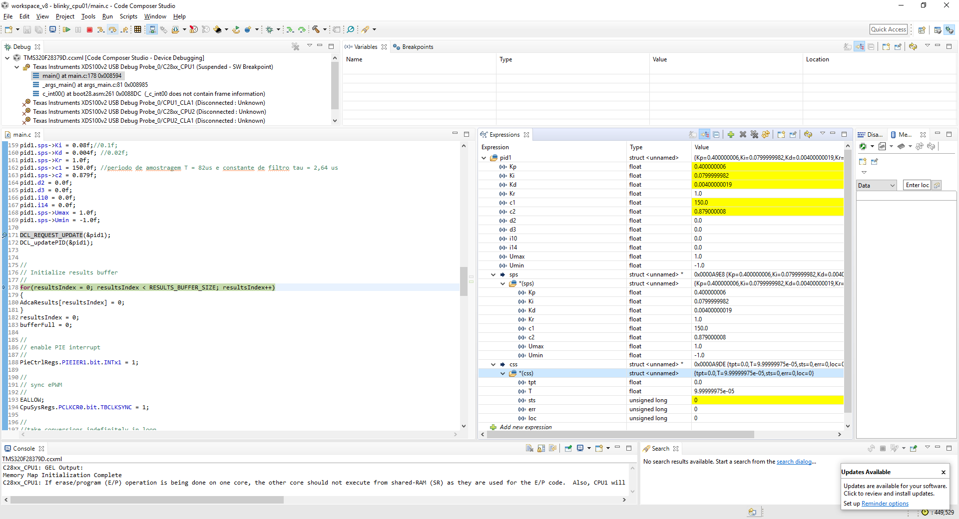
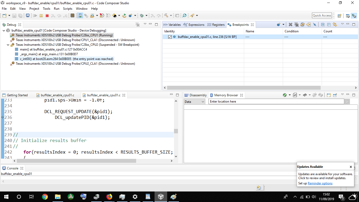
DCL_REQUEST_UPDATE(&pid1);
DCL_fupdatePID(&pid1);
My question about the last two line above. Am I right in writing them like just that or do I need to declare more functions ? Because in the watch window, the PID parameters do not udpate.
BR