This thread has been locked.
If you have a related question, please click the "Ask a related question" button in the top right corner. The newly created question will be automatically linked to this question.
Hi All
Looking for some beginner advise please in my new project in EV.
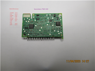
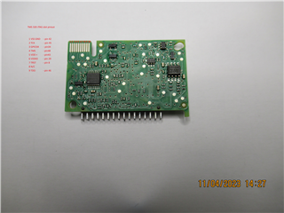
I have automotive PCB which contains TMS320F28034 and I would like to read :
----------------------------------------------
3D7800-3D7C00h | OTP Memory
3E8000-3F7FFFh | Flash Memory
----------------------------------------------
For this reason I purchased OLIMEX TMS320-XDS100-V2 https://www.olimex.com/Products/DSP/Emulators/TMS320-XDS100-V2
which suppose to be able read this MCU https://www.ti.com/product/de-de/TMS320F28034-Q1#description
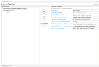
I try download and install CCS 12 but no ideas how I can read this MCU in ISP mode
I have pinout of JTAG
Battel plan is read and write to different device if OTP blank or blank into blank TMS320F28034
Please anyone can have me a hint how to use CSS12 and retrieve data from MCU please - will appreciate so much. ;)
Have nice day V.
Hi,
Please see this page to see how JTAG signals need to be connected between the PCB and your XDS100-v2: https://software-dl.ti.com/ccs/esd/documents/xdsdebugprobes/emu_xds_target_connection_guide.html#buffered-case
Once you have the hardware connection established, you can connect to the device using Code Composer Studio. To do this, you will need to make a new target configuration with the XDS100-v2 and the TMS320F28034. Then you will need to launch your target configuration, right-click on the C28xx core, and connect target. You should then be able to use the memory browser tool to save memory from the addresses you designate to the tool.
Please let me know if you need help with any of these steps.
Best Regards,
Ben Collier
Hello Again
finally I had time to return to project but problem to read over JTAG as below
but always have error and I am unable read this TMS320 :
Error connecting to the target: (Error -183 @ 0x0) The controller has detected a cable break far-from itself. The user must connect the cable/pod to the target. (Emulation package 9.12.0.00150)
Try change USB cable no change
Looks like drivers installed correctly
I connected to OLIMEX like this pinout
My JTAG have extra GPIO34 but no idea if need to be connected
#
Anyone have please any idea how to read this data please
Thank you for support community ;)
Hi,
If you have access to an oscilloscope, could you try probing TDO (yellow), TMS (purple), TCK (blue), and TRST (green) as shown below. The screenshot below was captured using the XDS100v2, and it was a single-capture triggered on the falling edge of TMS. Could you try doing the same and see if your probed signals look the same?
Best Regards,
Ben Collier
Hi ben THX for support
I try use scope and looks like signal is a same as yours
I been able only trigger on CH1 as picture but still no data retrieval from UniFlash just error 1041 @ 0xFFFFFF49
Hi Vladimir,
Your JTAG signals look as expected. Could you use CCS to look at your target configuration? Specifically, could you go to the advanced tab and look at the settings for the JTAG Debug Probe?
Also, do you see a different error if you try shorting TCK and RTCK on the debug probe?
Best Regards,
Ben Collier
Hello Benjamin
Right now I am using UNIFLASH I do not know how to use CSS for reading data
but here is my screenshot how is set up
This is a settings for UniFlash
BTW I try different OLIMEX TMS320-XDS100-V2 and is same signal and no date from flash
and If I short pins 9-11 RTCK and TCK still same signal on scope as well no read from FLASH
and error :
ERROR] C28xx: Error connecting to the target: (Error -1041 @ 0xFFFFFF49) The debug probe reported an error. Confirm debug probe configuration and connections, reset the debug probe, and retry the operation. (Emulation package 9.12.0.00150)
Vladimir,
Would you be able to try debugging in CCS since it will give more options for debugging. Once we have solved this issue, you could still use Uniflash to read the data, though you should be able to do so with CCS as well.
Could you try using the 'Test Connection' button in your target configuration file?
Best Regards,
Ben Collier
Hi again Benjamin
I try over CSS and same problem signal present on scope but no able read out TMS320
here is LOG:
[Start: Texas Instruments XDS100v2 USB Debug Probe_0]
Execute the command:
%ccs_base%/common/uscif/dbgjtag -f %boarddatafile% -rv -o -F inform,logfile=yes -S pathlength -S integrity
[Result]
-----[Print the board config pathname(s)]------------------------------------
C:\Users\VACE3~1.URG\AppData\Local\TEXASI~1\
CCS\ccs1240\0\0\BrdDat\testBoard.dat
-----[Print the reset-command software log-file]-----------------------------
This utility has selected a 100/110/510 class product.
This utility will load the adapter 'jioserdesusb.dll'.
The library build date was 'Sep 6 2023'.
The library build time was '09:57:39'.
The library package version is '9.13.0.00201'.
The library component version is '35.35.0.0'.
The controller does not use a programmable FPGA.
The controller has a version number of '4' (0x00000004).
The controller has an insertion length of '0' (0x00000000).
This utility will attempt to reset the controller.
This utility has successfully reset the controller.
-----[Print the reset-command hardware log-file]-----------------------------
The scan-path will be reset by toggling the JTAG TRST signal.
The controller is the FTDI FT2232 with USB interface.
The link from controller to target is direct (without cable).
The software is configured for FTDI FT2232 features.
The controller cannot monitor the value on the EMU[0] pin.
The controller cannot monitor the value on the EMU[1] pin.
The controller cannot control the timing on output pins.
The controller cannot control the timing on input pins.
The scan-path link-delay has been set to exactly '0' (0x0000).
-----[The log-file for the JTAG TCLK output generated from the PLL]----------
There is no hardware for programming the JTAG TCLK frequency.
-----[Measure the source and frequency of the final JTAG TCLKR input]--------
There is no hardware for measuring the JTAG TCLK frequency.
-----[Perform the standard path-length test on the JTAG IR and DR]-----------
This path-length test uses blocks of 64 32-bit words.
The JTAG IR instruction path-length was not recorded.
-----[Perform the Integrity scan-test on the JTAG IR]------------------------
This test will use blocks of 64 32-bit words.
This test will be applied just once.
Do a test using 0xFFFFFFFF.
Scan tests: 1, skipped: 0, failed: 0
-----[An error has occurred and this utility has aborted]--------------------
This error is generated by TI's USCIF driver or utilities.
The value is '-183' (0xffffff49).
The title is 'SC_ERR_CTL_CBL_BREAK_FAR'.
The explanation is:
The controller has detected a cable break far-from itself.
The user must connect the cable/pod to the target.
[End: Texas Instruments XDS100v2 USB Debug Probe_0]
Just Quick Q ? Is Flash location at 0x3E8000 - 0x3F7FFF ?
check_box Sector A: (0x3F6000 - 0x3F7FFF)
check_box Sector B: (0x3F4000 - 0x3F5FFF)
check_box Sector C: (0x3F2000 - 0x3F3FFF)
check_box Sector D: (0x3F0000 - 0x3F1FFF)
check_box Sector E: (0x3EE000 - 0x3EFFFF)
check_box Sector F: (0x3EC000 - 0x3EDFFF)
check_box Sector G: (0x3EA000 - 0x3EBFFF)
check_box Sector H: (0x3E8000 - 0x3E9FFF)