Other Parts Discussed in Thread: UNIFLASH, C2000WARE, CONTROLSUITE
Hello,
We are facing the same issue as the thread below, where the Flash cannot be programmed (see full provided log).
C28xx_CPU1: Error: (Error -1135 @ 0xC095) The debug probe reported an error. Confirm debug probe configuration and connections, reset the debug probe, and retry the operation. (Emulation package 8.4.0.00006)
C28xx_CPU1: Trouble Halting Target CPU: (Error -1044 @ 0x0) The debug probe reported an error. Confirm debug probe configuration and connections, reset the debug probe, and retry the operation. (Emulation package 8.4.0.00006)
C28xx_CPU1: Error: (Error -1135 @ 0xC095) The debug probe reported an error. Confirm debug probe configuration and connections, reset the debug probe, and retry the operation. (Emulation package 8.4.0.00006)
C28xx_CPU1: Unable to determine target status after 20 attempts
C28xx_CPU1: Failed to remove the debug state from the target before disconnecting. There may still be breakpoint op-codes embedded in program memory. It is recommended that you reset the emulator before you connect and reload your program before you continue debugging
C28xx_CPU1: Error occurred during flash operation: Could not read 0x0007026D@Data: target is not connected
C28xx_CPU1: Error occurred during flash operation: Could not write 0x0005F444@Data: target is not connected
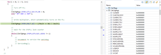
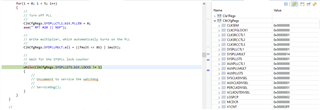
A break through during troubleshooting was when we were able to connect to the DSP with JTAG. We can step into a program loaded in RAM, everything run fine until we reach the instruction that set the PLL in order to increase the SYSCLK to 200MHz.
InitSysPll(XTAL_OSC,IMULT_20,FMULT_0,PLLCLK_BY_2) ;
Therefore, with this piece of information in mind, using UNIFLASH, we lowered the Flash programming clock to around 95MHz and we were able to program the FLASH. I don't think this is a solution since it never happened to us before. Although, it is a new set of custom boards to be programmed, the design hasn't changed for years and we don't feel comfortable with this approach especially that after programming we basically can't connect to the DSP via JTAG anymore and get the following error message:
(from https://software-dl.ti.com/ccs/esd/documents/ccsv7_debugging_jtag_connectivity_issues.html)
Invalid data read back
This error varies greatly depending on the type of fault and therefore both CCS and the Test Connection can return different results.
Common to all scenarios is when the integrity scan-test fails with invalid data - something mentioned in this e2e forum thread.
One example is a typical stuck-at-ones or stuck-at-zero fault, that can manifest in two ways:
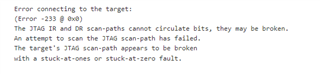
    Error connecting to the target:
    (Error -233 @ 0x0)
    The JTAG IR and DR scan-paths cannot circulate bits, they may be broken.
    An attempt to scan the JTAG scan-path has failed.
    The target's JTAG scan-path appears to be broken
    with a stuck-at-ones or stuck-at-zero fault.
I believe it might be related to the same issue.
We monitored all the power rails and we also provided the DSP with voltages straight from an external power supply, but nothing worked.
At this point we are running out of options and ideas and it is becoming very critical for the pursuit of our activities.
Does anyone know how to fix this issue? I only saw one thread that talks about it.
Thank you for your help, this is very important and critical.
C28xx_CPU1: Error: (Error -1135 @ 0xC095) The debug probe reported an error. Confirm debug probe configuration and connections, reset the debug probe, and retry the operation. (Emulation package 8.4.0.00006)
C28xx_CPU1: Trouble Halting Target CPU: (Error -1044 @ 0x0) The debug probe reported an error. Confirm debug probe configuration and connections, reset the debug probe, and retry the operation. (Emulation package 8.4.0.00006)
C28xx_CPU1: Error: (Error -1135 @ 0xC095) The debug probe reported an error. Confirm debug probe configuration and connections, reset the debug probe, and retry the operation. (Emulation package 8.4.0.00006)
C28xx_CPU1: Unable to determine target status after 20 attempts
C28xx_CPU1: Failed to remove the debug state from the target before disconnecting.  There may still be breakpoint op-codes embedded in program memory.  It is recommended that you reset the emulator before you connect and reload your program before you continue debugging
C28xx_CPU1: Error occurred during flash operation: Could not read 0x0007026D@Data: target is not connected
C28xx_CPU1: Error occurred during flash operation: Could not write 0x0005F444@Data: target is not connected
C28xx_CPU1: Error occurred during flash operation: Could not read 0x0005F444@Data: target is not connected
C28xx_CPU1: Error occurred during flash operation: Could not read 0x00130@Program: target is not connected
C28xx_CPU1: Error executing PLL configuration algorithm. Operation cancelled. (0x0)
C28xx_CPU1: Error occurred during flash operation: Could not write 0x0005D200@Data: target is not connected
C28xx_CPU1: File Loader: Memory write failed: Unknown error
C28xx_CPU1: GEL: File: C:\Users\bryan.irwin\Desktop\magniDrive ATP\SW Images\uSW_Images_release\Tier1-250_INV1.hex: Load failed.
C28xx_CPU1: Error occurred during flash operation: Could not read register PC: target is not connected
C28xx_CPU1: Error occurred during flash operation: Could not write 0x0005F800@Data: target is not connected
C28xx_CPU1: Error occurred during flash operation: Could not write 0x00000@Program: target is not connected
C28xx_CPU1: Error occurred during flash operation: Cannot enable while the target is disconnected
C28xx_CPU1: Error occurred during flash operation: Could not read 0x0005F444@Data: target is not connected
C28xx_CPU1: Error occurred during flash operation: Could not read 0x0007026D@Data: target is not connected
C28xx_CPU1: Error occurred during flash operation: Could not write 0x0005F444@Data: target is not connected
C28xx_CPU1: Error occurred during flash operation: Could not read 0x0005F444@Data: target is not connected
C28xx_CPU1: Error occurred during flash operation: Failed to run target while trying to execute pwrite_en.alg
C28xx_CPU1: Flash operation timed out waiting for the algorithm to complete. Operation cancelled.
C28xx_CPU1: Perform a debugger reset and execute the Boot-ROM code (click on the RESUME button in CCS debug window) before erasing/loading the Flash.  If that does not help to perform a successful Flash erase/load, check the Reset cause (RESC) register, NMI shadow flag (NMISHDFLG) register and the Boot-ROM status register for further debug.
C28xx_CPU1: Error occurred during flash operation: Could not read 0x0007026D@Data: target is not connected
C28xx_CPU1: Error occurred during flash operation: Could not write 0x0005F444@Data: target is not connected
C28xx_CPU1: Error occurred during flash operation: Could not read 0x0005F444@Data: target is not connected
C28xx_CPU1: Error occurred during flash operation: Could not read 0x0007026D@Data: target is not connected
C28xx_CPU1: Error occurred during flash operation: Could not write 0x0005D200@Data: target is not connected
C28xx_CPU1: Error occurred during flash operation: Could not read 0x5D200@Program: target is not connected
C28xx_CPU1: Error occurred during flash operation: Could not read 0x0007026D@Data: target is not connected
C28xx_CPU1: Error occurred during flash operation: Could not read 0x0005D20E@Data: target is not connected
C28xx_CPU1: Error occurred during flash operation: Could not write 0x0005D20E@Data: target is not connected
C28xx_CPU1: Error occurred during flash operation: Could not read 0x0005D20E@Data: target is not connected
C28xx_CPU1: Error occurred during flash operation: Could not write 0x0005D20E@Data: target is not connected
C28xx_CPU1: Error occurred during flash operation: Could not read 0x0005D22E@Data: target is not connected
C28xx_CPU1: Error occurred during flash operation: Could not read 0x0005D208@Data: target is not connected
C28xx_CPU1: Error occurred during flash operation: Could not write 0x0005D208@Data: target is not connected
C28xx_CPU1: Error occurred during flash operation: Could not read 0x0005D208@Data: target is not connected
C28xx_CPU1: Error occurred during flash operation: Could not write 0x0005D208@Data: target is not connected
C28xx_CPU1: Error occurred during flash operation: Could not read 0x0005D222@Data: target is not connected
C28xx_CPU1: Error occurred during flash operation: Could not write 0x0005D222@Data: target is not connected
C28xx_CPU1: Error occurred during flash operation: Could not write 0x0005D214@Data: target is not connected
C28xx_CPU1: Error occurred during flash operation: Could not read 0x0005D20E@Data: target is not connected
C28xx_CPU1: Error occurred during flash operation: Could not write 0x0005D20E@Data: target is not connected
C28xx_CPU1: Error occurred during flash operation: Could not write 0x0005D20E@Data: target is not connected
C28xx_CPU1: Error occurred during flash operation: Could not write 0x0005D222@Data: target is not connected
C28xx_CPU1: Error occurred during flash operation: Could not write 0x0005D200@Data: target is not connected
C28xx_CPU1: Error occurred during flash operation: Could not write 0x00000@Program: target is not connected
C28xx_CPU1: Error occurred during flash operation: Cannot enable while the target is disconnected
C28xx_CPU1: Error occurred during flash operation: Could not read 0x0005F444@Data: target is not connected
C28xx_CPU1: Error occurred during flash operation: Could not read 0x0007026D@Data: target is not connected
C28xx_CPU1: Error occurred during flash operation: Could not write 0x0005F444@Data: target is not connected
C28xx_CPU1: Error occurred during flash operation: Could not read 0x0005F444@Data: target is not connected
C28xx_CPU1: Error occurred during flash operation: Failed to run target while trying to execute pwrite_dis.alg
C28xx_CPU1: Flash operation timed out waiting for the algorithm to complete. Operation cancelled.
C28xx_CPU1: Perform a debugger reset and execute the Boot-ROM code (click on the RESUME button in CCS debug window) before erasing/loading the Flash.  If that does not help to perform a successful Flash erase/load, check the Reset cause (RESC) register, NMI shadow flag (NMISHDFLG) register and the Boot-ROM status register for further debug.
C28xx_CPU1: Error occurred during flash operation: Could not read 0x0007026D@Data: target is not connected
C28xx_CPU1: Error occurred during flash operation: Could not write 0x0005F444@Data: target is not connected
C28xx_CPU1: Error occurred during flash operation: Could not read 0x0005F444@Data: target is not connected
C28xx_CPU1: Error occurred during flash operation: Could not write register PC: target is not connected