Other Parts Discussed in Thread: CONTROLSUITE, TIDM-HV-1PH-DCAC
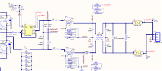
controlSUITE\development_kits\HV_1PH_DCAC\v1_02_00_00\hardware\r3\TIDM-HV-1PH-DCAC-SCH.PDF
Some problems of about TIDM-HV-1PH-DCAC-SCH.PDF
Design Guide: TIDM-HV-1PH-DCAC
Voltage Source Inverter Reference Design
Description
This reference design implements single-phase
inverter (DC/AC) control using a C2000
microcontroller (MCU). The design supports two
modes of operation for the inverter: a voltage source
mode using an output LC filter
High-efficiency, low
THD, and intuitive software make this design attractive
for engineers working on an inverter design for UPS
So some questions are as follows(about a voltage source mode using an output LC filter,TIDM-HV-1PH-DCAC-SCH.pdf)
C4,C8,C13,C14 ,L2,L4 Can these components be eliminated?What would be the impact if these components were removed?
c1 is 20uf?
Can the common mode inductance work if there is no grounding point in the entire system?