This thread has been locked.
If you have a related question, please click the "Ask a related question" button in the top right corner. The newly created question will be automatically linked to this question.
Hello I'm experiencing a duty cycle issue during the phase transition, and I would like to hear your opinions.
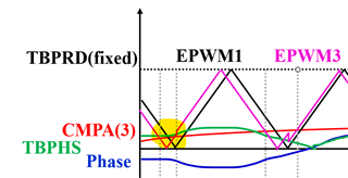
I'm using updown counter for all EPWM channel. The orange represents EPWM3, and the gray represents EPWM4 channels. I've set EPWM1 as a reference to adjust the phase of EPWM3 and EPWM4. In the section of the image, the duty cycle of EPWM3 is approximately d3=0.1, and EPWM4 should switch complementarily with 1-d3.
However, the issue arises in the highlighted red rectangle. The duty cycle of EPWM3 should be around 0.1, but suddenly it becomes 1 in that region. Despite limiting the duty cycle of EPWM to a maximum of 0.5, it unexpectedly reaches 1. This problem doesn't persist but occurs sporadically even though it generally operates well.
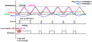
This problem seems to occur when using phase shift, and it works fine when phase shift is not applied. Moreover, during this time, when the phase transitions from positive to negative, it seems to have an impact.
please see the code below.
-------------------------------------------------------------------------------------------------------------------------
//EPWM set
// Updown
ePWM_Regs[ch]->AQCTLA.bit.CAD = AQ_SET;
ePWM_Regs[ch]->AQCTLA.bit.CAU = AQ_CLEAR;
ePWM_Regs[ch]->AQCTLB.bit.CAD = AQ_SET;
ePWM_Regs[ch]->AQCTLB.bit.CAU = AQ_CLEAR;
if(ch==1 ){
ePWM_Regs[ch]->TBCTL.bit.PHSEN = 0;//TB_DISABLE;
ePWM_Regs[ch]->TBCTL.bit.SYNCOSEL =1;// TB_CTR_ZERO;
}
else if(ch!=1) {
ePWM_Regs[ch]->TBCTL.bit.PHSEN = 1;//TB_ENABLE;
ePWM_Regs[ch]->TBCTL.bit.SYNCOSEL = 0;//TB_SYNC_IN;
}
SyncSocRegs.SYNCSELECT.bit.SYNCOUT = 0x2; //(enable)
// Setup TBCLK
ePWM_Regs[ch]->TBCTL.bit.CTRMODE = 2;//TB_COUNT_UPDOWN; // Count up-down
ePWM_Regs[ch]->TBCTL.bit.PRDLD = 0;//TB_SHADOW;
ePWM_Regs[ch]->TBCTL.bit.HSPCLKDIV = 0;//TB_DIV1;
ePWM_Regs[ch]->CMPCTL.bit.SHDWAMODE = 0;//CC_SHADOW;
ePWM_Regs[ch]->CMPCTL.bit.SHDWBMODE = 0;//CC_SHADOW;
ePWM_Regs[ch]->CMPCTL.bit.LOADAMODE = 0;//CC_CTR_ZERO;
ePWM_Regs[ch]->CMPCTL.bit.LOADBMODE = 0;//CC_CTR_ZERO;
ePWM_Regs[ch]->DBCTL.bit.IN_MODE = 2;//DBA_RED_DBB_FED;
ePWM_Regs[ch]->DBCTL.bit.POLSEL = 2;//DB_ACTV_HIC;
ePWM_Regs[ch]->DBCTL.bit.OUT_MODE = 3;//DB_FULL_ENABLE;
----------------------------------------------------------------------------------------
//phase shift setting
if(phase == 0) ePWM_Regs[ch]->TBPHS.bit.TBPHS = 0;
else if(phase > 0){
ePWM_Regs[ch]->TBCTL.bit.PHSDIR = 0;
ePWM_Regs[ch]->TBPHS.bit.TBPHS = (int16)((float32)ePWM_Regs[ch]->TBPRD * phase * 0.00277777);
}
else {
ePWM_Regs[ch]->TBCTL.bit.PHSDIR = 1;
ePWM_Regs[ch]->TBPHS.bit.TBPHS = (int16)((float32)ePWM_Regs[ch]->TBPRD * -phase * 0.00277777);
}
-----------------------------------------------------------------------------------------------------
//duty setting
ePWM_Regs[ch]->CMPA.bit.CMPA = (Uint32)((float32)ePWM_Regs[ch]->TBPRD * duty);
---------------------------------------------------------------------------------------------------------
Hi Song,
Thanks for your patience over the holiday week. To clarify, does this single 100% duty cycle on EPWM3 occur only when you are trying to change/update the phase shift value? And then after this, the EPWM signals are running correctly with the updated phase shift values? Would it be possible for you to provide a scope shot that includes the syncout pulse when EPWM1 TBCTR=0 occurs? Some other initial questions: When are you changing the phase value, and what value do you change it to (i.e. what is the value of your TBPRD and the "phase" variable?). Perhaps there is an action qualifier being missed when the phase change occurs, but I'd like to better understand the order of events. Out of curiosity, have you tried using different settings for when the synchronization and/or shadow loading occur other than CTR=0?
Best Regards,
Allison
yes it occur only some specific phase shift value. and epwm are shifted well by my phase shift value that the ouput PI controller. And i'm trying to give you scopeshot. but i'm using ccs its hard to take a photo.
phase value updated per 20kHz(sampling frequency) and phase value is the output of PI controller. i add some photo. And i only using synchronization when CTR=0.
Hi Song,
Do you have access to be able to use an oscilloscope? I think that might be easier for you to watch the signals. What are your TBPRD and CMPx values set at and what is the EPWMCLK? (looks like TBPRD is 664?) Are you able to know what specific phase shift value the issue occurs at? Also, another setting to try is shadow loading on both CTR=0 and PRD setting.
Best Regards,
Allison
Hi Allison,
I'll take a photo asap, and i'll show you.
TBPRD is output of PI controller. and the value is not constant, it can move from -240 to 240. CMPA range is 66 to 332. CMPA's shape is sinusoidal. EPWMCLK is 200MHz. And my switching frequency is 150kHz.
I want to find that value, but when I incremented the bits one by one(constant phase), there was no issue, but problems occurred when using a PI controller.
Thank you very much. I'll try to load shadow both side.
Best Regards,
Song
Hi Song,
when I incremented the bits one by one(constant phase)
When you say this, do you mean you are incrementing both TBPRD and CMPA and disabling phase shift?
EPWMCLK is 200MHz
Please also note that the maximum EPWMCLK should be 100MHz as specified in this device datasheet - I would adjust so that you meet this requirement, otherwise you are out of spec. Please let me know if this changes the behavior you see.
Best Regards,
Allison
Hi Allison,
Im sorry. There was my mistake. TBPRD is fixed value. TBPHS is output of PI controller. And I want to find a specific phase shift value. so i incremented TBPHS one by one. not TBPRD. set CMPA , TBPRD and other things same. But there was no duty error. so i cannot find the phase shift value. it only occurs when using TBPHS value that from PI controller.
I did not know about that.. I will change 100MHz.Thank you so much.
Best Regards,
Song
Hi Song,
No worries, thanks for the clarification. Were you able to change to 100MHz EPWMCLK? Let me know if this changes the issue you see since sometimes that can cause unexpected behavior.
Best Regards,
Allison
Hi Allison,
I'm sorry for late response. I changed to 100MHz EPWMCLK. But the problem is actually same. Some Duty error in one switch, in PWM. Can you know me next step? Thank you so much.
Best Regards,
Song
Hi Song,
Thanks for getting back to me. It's best to stay in spec with the 100MHz EPWMCLK - let's see if we can continue debugging the issue.
When are you syncing to cause the phase shift? Would you be able to draw a quick diagram of what you are trying to accomplish showing the timing of when the counter = 0, TBPRD, CMPAU, CMPAD events, sync events, and when you update the TBPHS value? Sometimes the timing of these can cause issues.
Can I also ask if you've tried referencing any of the C2000Ware examples? There is a driverlib example that implements phase shift: epwm_ex3_synchronization.c located at {C2000Ware}\driverlib\f2837xd\examples\cpu1\epwm. And there are other driverlib examples located at that directory and more bitfield examples located in the device support folder of C2000Ware.
Best Regards,
Allison
Hi Allison,
I draw diagram regarding the timing you mentioned. Is this what you were looking for?
First, let me explain the diagram. I use up-down counter for EPWM. Black up-down counter is EPWM1 and pink one is EPWM3. EPWM3 is phase shifted by TBPHS regarding to EPWM1. And red one is CMPA and Blue one is Phase. Green one is TBPHS.
I use fixed frequency, 150kHz. So TBPRD is fixed. I change only phase and duty cycle. But phase and duty cycle are not fixed they are variable by time and controller.EPWM3A and EPWM3B is switching complimentary. TBPHS is Full-Wave of Phase. I make TBPHS full wave of Phase (TBPHS= -Phase), PHSDIR=1 when Phase<0. And when Phase>0 I set TBPHS=Phase , PHSDIR=0.
While drawing it, I understood that issues related to timing could lead to duty cycle problems. When sync in, TBPHS is updated and TBCTR and CMPA could not match. However, I'm unsure about the solution. Could you provide guidance on the next steps?
I knew there are library examples. But I didn't know there are C2000 bitfield examples. I'll find and apply directly. Thank you so much.
Best Regards,
Song
Hi Song,
The diagram does help my understanding, thank you for sending. Let me know if you are able to leverage some of our existing examples or have questions there!
How are you changing your CMPA and TBPHS values - are they updated in an ISR? Would you be able to share the code?
My thoughts are if you are setting high on CMPA-down, clearing on CMPA-up with a changing CMPA and TBPHS, you could be missing an action qualifier. This could happen for example if your TBPHS is greater than your CMPA, meaning that when there is a sync on CTR=0, the CTR jumps to a number larger than CMPA and misses the "clear" action when CTR=CMPA. Let me also discuss with some other experts on this and get back to you tomorrow.
Best Regards,
Allison
Hi Allison,
Thanks for your professional explanation. Now I can understand the problem well.
CMPA and TBPHS values are updated in an ISR. I use ADC Interrupt.
This is my code but I remain only important.
//=================EPWM setting====================// void conf_ePWM_Sym(Uint16 ch, float32 freq) //EPWM1, EPWM2 { // Set actions ePWM_Regs[ch]->AQCTLA.bit.CAD = 2; //AQ_SET ePWM_Regs[ch]->AQCTLA.bit.CAU = 1; //AQ_CLEAR ePWM_Regs[ch]->AQCTLB.bit.CBD = 2; //AQ_SET ePWM_Regs[ch]->AQCTLB.bit.CBU = 1; //AQ_CLEAR if(ch==1 ){ ePWM_Regs[ch]->TBCTL.bit.PHSEN = 0; //TB_DISABLE ePWM_Regs[ch]->TBCTL.bit.SYNCOSEL = 1; //TB_CTR_ZERO ePWM_Regs[ch]->TBPHS.bit.TBPHS = 0; } else { ePWM_Regs[ch]->TBCTL.bit.PHSEN = 1; //TB_ENABLE ePWM_Regs[ch]->TBCTL.bit.SYNCOSEL = 0; //TB_SYNC_IN ePWM_Regs[ch]->TBCTL.bit.PHSDIR = 0; //TB_DOWN } // Setup TBCLK ePWM_Regs[ch]->TBCTL.bit.CTRMODE = 2; //TB_COUNT_UPDOWN // Count up-down ePWM_Regs[ch]->TBCTL.bit.PRDLD = 0; //TB_SHADOW ePWM_Regs[ch]->TBCTL.bit.HSPCLKDIV = 0; //TB_DIV1 ePWM_Regs[ch]->CMPCTL.bit.SHDWAMODE = 0; //CC_SHADOW // Load registers every ZERO ePWM_Regs[ch]->CMPCTL.bit.SHDWBMODE = 0; //CC_SHADOW ePWM_Regs[ch]->CMPCTL.bit.LOADAMODE = 0; //CC_CTR_ZERO ePWM_Regs[ch]->CMPCTL.bit.LOADBMODE = 0; //CC_CTR_ZERO ePWM_Regs[ch]->DBCTL.bit.IN_MODE = 2; //DBA_RED_DBB_FED ePWM_Regs[ch]->DBCTL.bit.POLSEL = 2; //DB_ACTV_HIC ePWM_Regs[ch]->DBCTL.bit.OUT_MODE = 3; //DB_FULL_ENABLE //deadtime updateDuty_Sym(ch, 0.0); updatePhase(ch, 0.0); updateFreq(ch, freq); updateDeadtime(ch, 0.0); } void conf_ePWM_Asym(Uint16 ch, float32 freq) //EPWM3,4 { // Set actions ePWM_Regs[ch]->AQCTLA.bit.CAD = 2; //AQ_SET ePWM_Regs[ch]->AQCTLA.bit.CAU = 1; //AQ_CLEAR ePWM_Regs[ch]->AQCTLB.bit.CAD = 2; //AQ_SET ePWM_Regs[ch]->AQCTLB.bit.CAU = 1; //AQ_CLEAR if(ch==1){ ePWM_Regs[ch]->TBCTL.bit.PHSEN = 0; //TB_DISABLE ePWM_Regs[ch]->TBCTL.bit.SYNCOSEL = 1; //TB_CTR_ZERO ePWM_Regs[ch]->TBPHS.bit.TBPHS = 0; } else { ePWM_Regs[ch]->TBCTL.bit.PHSEN = 1; //TB_ENABLE } // Setup TBCLK ePWM_Regs[ch]->TBCTL.bit.CTRMODE = 2; //TB_COUNT_UPDOWN // Count up-down ePWM_Regs[ch]->TBCTL.bit.PRDLD = 0; //TB_SHADOW ePWM_Regs[ch]->TBCTL.bit.HSPCLKDIV = 0; //TB_DIV1 ePWM_Regs[ch]->CMPCTL.bit.SHDWAMODE = 0; //CC_SHADOW // Load registers every ZERO ePWM_Regs[ch]->CMPCTL.bit.SHDWBMODE = 0; //CC_SHADOW ePWM_Regs[ch]->CMPCTL.bit.LOADAMODE = 0; //CC_CTR_ZERO ePWM_Regs[ch]->CMPCTL.bit.LOADBMODE = 0; //CC_CTR_ZERO ePWM_Regs[ch]->DBCTL.bit.IN_MODE = 2; //DBA_RED_DBB_FED ePWM_Regs[ch]->DBCTL.bit.POLSEL = 2; //DB_ACTV_HIC ePWM_Regs[ch]->DBCTL.bit.OUT_MODE = 3; //DB_FULL_ENABLE //deadtime updateDuty_Asym(ch, 0.0); updateFreq(ch, freq); updateDeadtime(ch, 0.0); } void updateDuty_Sym(Uint16 ch, float32 duty) //EPWM1 and EPWM2 duty { ePWM_Regs[ch]->CMPA.bit.CMPA = (Uint32)((float32)ePWM_Regs[ch]->TBPRD * duty); ePWM_Regs[ch]->CMPB.bit.CMPB = (Uint32)((float32)ePWM_Regs[ch]->TBPRD * (1-duty)); } void updateDuty_Asym(Uint16 ch, float32 duty) //EPWM3 and EPWM4 duty { ePWM_Regs[ch]->CMPA.bit.CMPA = (Uint32)((float32)ePWM_Regs[ch]->TBPRD * duty); } void updatePhase(int16 ch, float32 phase) /Phase Shift { if(phase == 0)ePWM_Regs[ch]->TBPHS.bit.TBPHS = 0; else if(phase > 0){ ePWM_Regs[ch]->TBCTL.bit.PHSDIR = 0; ePWM_Regs[ch]->TBPHS.bit.TBPHS = (int16)((float32)ePWM_Regs[ch]->TBPRD * phase * 0.00555555); } else if (phase<0){ ePWM_Regs[ch]->TBCTL.bit.PHSDIR = 1; ePWM_Regs[ch]->TBPHS.bit.TBPHS = (int16)((float32)ePWM_Regs[ch]->TBPRD * -phase * 0.00555555); } } //=======================================// interrupt void adcA_isr(void) //adc interrupt { switch(operationMode) { case DC2AC: dsa= fabs(0.5*sin(60wt)) //dsa is full-wave of 0.5sin and its frequency is 60Hz Phase_ref_a = PIcon(Vcom,Vref,err,gain) //Phase_ref_a is output of PI controller updateDuty_Sym(1, 0.5); updateDuty_Sym(2, 0.5); updateDuty_Asym(7,dsa); updateDuty_Asym(8,dsa); updatePhase(2,180); updatePhase(7, Phase_ref_a); updatePhase(8,180 + Phase_ref_a); break; } } //PI controller// float PIcon(float ref, float in, struct PID_ERRORS *error, struct PID_GAINS K) { float32 out; error->e = ref - in; error->sum += (error->e - error->w) * K.I * SAMPLING_TIME; out = (K.P * error->e) + error->sum; return out; }
I hope it helps we solve the problem.
Best Regards,
Song
Hi Song,
Thanks for sharing the code - I will take a closer look. Can you please let me know what the CMPA and TBPHS values are when the longer pulse occurs? Is it only when TBPHS = 0?
Best Regards,
Allison
Hi Allison,
Sorry, but I couldn't pinpoint the exact value. The issue generally occurs with CMPA close to the minimum, around 65 in my case. At that point, TBPHS seems to be in the range of 15 to 20. However, I couldn't determine the precise value.
I am currently setting up to monitor TBPHS and CMPA values through the scope. I will let you know shortly.
Best Regards,
Song
Hi Song,
Here are a few recommendations in debugging to try to simplify your program and narrow down the cause and case:
Also I want to double check that you are not actually loading TBPHS with negative values, correct? TBPHS should always be positive since the TBCTR is loaded with this value upon sync pulse.
Best Regards,
Allison
Hi Allison,
1,2. I try 1 and 2 method that fixing constant CMPA(TBPHS) and TBPHS(CMPA) is varying. And there is no PWM skipping.
But this is not my goal modulation, it makes my products performance bad.. I want to make CMPA and TBPHS vary at the same time.
3. I don't understand what is "good" value. TBPHS and CMPA value is correct, they are what i want. I wonder i have to change my switching modulation.
TBPHS is not negative value. I'm watching CMPA and TBPHS bit value in CCS debug mode.
Best Regards,
Song
Hi Song,
Thanks for getting back to me and for trying out the first methods 1 and 2. This helps us to understand that the issue is when both TBPHS and CMPA are changing. With TBPHS and CMPA values both changing, certain combinations can cause a missing Action Qualifier such as, for example, on the first cycle that TBPHS exceeds CMPA (which can cause a long PWM pulse due to the missing AQ).
Here are some suggestions to try to resolve it:
Let me know if you are able to use the T1 event here.
Best Regards,
Allison
Hi Allison,
I have a few questions regarding creating T1, so I would like to inquire.
I understand "If the count direction on a SYNC event is up and TBPHS is larger than CMPA" --> this make problem. because it make PWM turn on missing Action Qualifier. Is it right?
And "T1 event should cause the same Action Qualifier that CMPA-up does." --> I think i have to EPWM3A turned off. So i think there will be 2 ways.
<If the count direction on a SYNC event is up and TBPHS is larger than CMPA>
1. Make EPWM3A forced off when sync in (can i do it? i don't know way)
2. Make CMPA3 = TBPHS+1 (can match TBCTR with CMPA when syncin)
which on is better way you think? Could you provide comments on it?
And I input my code i wrote by 2. I try to make T1 in the situation what you said. I'll appreciate if you read this and provide some comments.
int CMPA = (Uint32)((float32)ePWM_Regs[ch]->TBPRD * duty); //calculating CMPA bit int CMPB = (Uint32)((float32)ePWM_Regs[ch]->TBPRD *(1 - duty)); //calculating CMPB bit int TBPHS; if(phase < 0){ TBPHS = (int16)((float32)ePWM_Regs[ch]->TBPRD * -phase * 0.00555555); //calculating TBPHS bit } else{ TBPHS = (int16)((float32)ePWM_Regs[ch]->TBPRD * phase * 0.00555555); //calculating TBPHS bit } if( ePWM_Regs[ch]->TBSTS.bit.CTRDIR == 0){//down if(TBPHS > CMPA) { ePWM_Regs[ch]->CMPA.bit.CMPA = CMPA; ePWM_Regs[ch]->CMPB.bit.CMPB = CMPB; } else //T1 occur { ePWM_Regs[ch]->CMPA.bit.CMPA = TBPHS+1; //complimentary switching ePWM_Regs[ch]->CMPB.bit.CMPB = TBPHS-2; //complimentary switching } } else if(ePWM_Regs[ch]->TBSTS.bit.CTRDIR == 1){//up if(TBPHS > CMPA) //T1 occur { ePWM_Regs[ch]->CMPA.bit.CMPA = TBPHS-1; ePWM_Regs[ch]->CMPB.bit.CMPB = TBPHS+2; } else { ePWM_Regs[ch]->CMPA.bit.CMPA = CMPA; //complimentary switching ePWM_Regs[ch]->CMPB.bit.CMPB = CMPB; //complimentary switching } }
But I didn't try because now I have no switch, I can't try anymore. I'd like to try it when I'm sure. I'll ask for your understanding.
Best Regards,
Song
Hi Song,
I understand "If the count direction on a SYNC event is up and TBPHS is larger than CMPA" --> this make problem. because it make PWM turn on missing Action Qualifier. Is it right?
Yes, this is correct. Below I also sketched a quick, simple case of how a missing action can occur (the below example has the counter count down after a sync event) similar to your sketch earlier. You can see where the red CMPAD event is skipped because the TBCTR jumps over CMPA when the green SYNC pulse occurs:
Also apologies, yes I should have clarified that in order to implement T1 in a system where you are constantly updating TBPHS and CMPA (such as in your case), you would need to enable and disable T1 via software by comparing TBPHS and CMPA values during each period similar to what you are doing in the code you attached.
Looking at your code, though, it seems you are adjusting CMPA and CMPB instead of using the T1 event. Was that intentional? I would recommend you configure the T1 event event of the Action Qualifier submodule - see TRM Action Qualifier section descriptions. You can select EPWMxSYNCI as the T1 event source. Then you can set the necessary action in your if/else loops depending on the TBPHS and CMPA. In this way, the action from a T1 event would supplement what the missing CMPA action would have done. Let me know if you need more clarification here.
Best Regards,
Allison