This thread has been locked.

If you have a related question, please click the "Ask a related question" button in the top right corner. The newly created question will be automatically linked to this question.

TMS320LF2407A:There is a strange phenomenon with the ADC.

Part Number: TMS320LF2407A
Other Parts Discussed in Thread: LM358, LM2904

hello.

Until now, we have been selling products using the 2407A.
Recently, it has been confirmed that the ADC operates abnormally at certain values.
I checked the CPU I purchased several years ago, but the same phenomenon appeared, with only a difference in degree.
Until now, it seems that it has gone unnoticed due to abnormalities in areas where it is not commonly used.

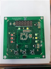
The phenomenon occurs when you gradually increase the voltage at the ADC input pin and observe the AD value, and it is read as shown in the photo below. (In the photo, 0 is the value of RESULT0 and 15 is the value of RESULT15.)


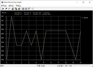
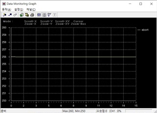
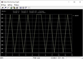
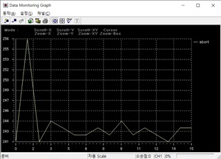
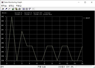
The value is fixed for a certain period at 256.
All values between 245 and 256 appear to be read as 256.
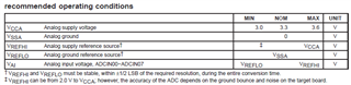
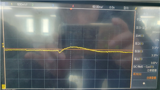
If you measure the voltage of the CPU ADC input, it is linear and normal.

The program used for observation is as follows.


if(AD_StartOk == 1)
{

temp = ADCTRL2 & 0x0200; // check the INT flag SEQ1

while (temp==0)
{
temp = ADCTRL2 & 0x0200; // check the INT flag SEQ1
}

SET(ADCTRL2,BIT9); // This INT FALG bit must be cleared by the user writing a 1 to it

AD_all_sum_result_value = 0;
AD_all_sum_result_value = ((RESULT0>>6)&0x3FF);
TEST[0] = AD_all_sum_result_value;
AD_all_sum_result_value = ((RESULT1>>6)&0x3FF);
TEST[1] = AD_all_sum_result_value;
AD_all_sum_result_value = ((RESULT2>>6)&0x3FF);
TEST[2] = AD_all_sum_result_value;
AD_all_sum_result_value = ((RESULT3>>6)&0x3FF);
TEST[3] = AD_all_sum_result_value;
AD_all_sum_result_value = ((RESULT4>>6)&0x3FF);
TEST[4] = AD_all_sum_result_value;
AD_all_sum_result_value = ((RESULT5>>6)&0x3FF);
TEST[5] = AD_all_sum_result_value;
AD_all_sum_result_value = ((RESULT6>>6)&0x3FF);
TEST[6] = AD_all_sum_result_value;
AD_all_sum_result_value = ((RESULT7>>6)&0x3FF);
TEST[7] = AD_all_sum_result_value;
AD_all_sum_result_value = ((RESULT8>>6)&0x3FF);
TEST[8] = AD_all_sum_result_value;
AD_all_sum_result_value = ((RESULT9>>6)&0x3FF);
TEST[9] = AD_all_sum_result_value;
AD_all_sum_result_value = ((RESULT10>>6)&0x3FF);
TEST[10] = AD_all_sum_result_value;
AD_all_sum_result_value = ((RESULT11>>6)&0x3FF);
TEST[11] = AD_all_sum_result_value;
AD_all_sum_result_value = ((RESULT12>>6)&0x3FF);
TEST[12] = AD_all_sum_result_value;
AD_all_sum_result_value = ((RESULT13>>6)&0x3FF);
TEST[13] = AD_all_sum_result_value;
AD_all_sum_result_value = ((RESULT14>>6)&0x3FF);
TEST[14] = AD_all_sum_result_value;
AD_all_sum_result_value = ((RESULT15>>6)&0x3FF);
TEST[15] = AD_all_sum_result_value;

Is there anything I can check?

  • Young,

              Are you saying the DC voltage present at the ADC input pins is correct but the corresponding (converted) digital value is incorrect? Could you please provide answers to the following questions?


    1. How long has this design been in production?
    2. If this design is in production, how many boards have been shipped with this device till date?
    3. In how many boards is this problem seen? What is the DPPM value?
    4. In a board where the problem is seen, is the problem intermittent or permanent?
    5. If the problem is intermittent, how often is it seen?
    6. Is it possible to reproduce the problem easily and consistently?
    7. Is this seen in a device that has been working fine for some time? If so, how long?
    8. What is the exact nature of failure?
    9. Are there any pins that are driven before the device is fully powered up? i.e. the rails have reached their final steady-state value?
    10. Are any pins treated in violation of the VIH/VIL specifications stated in the datasheet? For example, is a 5v level signal fed into any input pin?
    11. Is there any temperature dependency to the issue? i.e. does the rate of problem occurrence vary based on the ambient temperature?
    12. Would you be willing to share the schematics with us?
    13. Can you send a photo of the top side of the failing devices?
  • I have confirmed that there has been no change to the manufacturing site or our test process. We have not heard of similar issues with any other customer.

    1. How long has this design been in production?
      1. There have been no hardware revisions since 2012.
    2. If this design is in production, how many boards have been shipped with this device till date?
      1. The number of products delivered since 2012 is approximately 10,000 units.
    3. In how many boards is this problem seen? What is the DPPM value?
      1. Appears in all products. However, there is some difference in degree. For example, in the data in the previously attached photo, the value of 244 to 256 is fixed to 256, but for a good product, the value of 251 to 256 is fixed to 256.
    4. In a board where the problem is seen, is the problem intermittent or permanent?
      1. Appears in all products.
    5. If the problem is intermittent, how often is it seen?
      1. Appears in all products.
    6. Is it possible to reproduce the problem easily and consistently?
      1. Yes, if the value of 244~256 is fixed to 256 on the board, the same phenomenon will continue to occur in the same section.
        Additional testing is underway. The test will record the values of one board showing good behavior and one board showing bad behavior, and replace the two boards with CPUs from the same lot to see if there is any change in behavior.
        We will share it after confirmation.
    7. Is this seen in a device that has been working fine for some time? If so, how long?
      1. It is presumed that this has been the case continuously since ancient times.
        Previously, AD values around 256 were not important. However, recently values around 256 have been used and the phenomenon has been observed.
    8. What is the exact nature of failure?
      1. As mentioned earlier, the AD value of some sections is fixed to 256.
    9. Are there any pins that are driven before the device is fully powered up? i.e. the rails have reached their final steady-state value?
      1. How do I check whether the rail has reached steady state?
        However, there is initialization logic that requires time, such as memory initialization, after DSP Init. After that, the external watchdog pin is activated (it is the first pin to be driven) and the external chips are initialized. There doesn't seem to be any difference from the flow that is generally used.
    10. Are any pins treated in violation of the VIH/VIL specifications stated in the datasheet? For example, is a 5v level signal fed into any input pin?
      1. doesn't exist.
    11. Is there any temperature dependency to the issue? i.e. does the rate of problem occurrence vary based on the ambient temperature?
      1. It has nothing to do with temperature.
    12. Would you be willing to share the schematics with us?
      1. We are receiving several types of analog signals. Thermocouple, PT-100, 4~20mA, 0~5V However, since this phenomenon is the same for all types of sensors, we believe it is unrelated to the analog circuit. It doesn't make sense to look at all the circuits, so I'll share the circuit for one signal.
    13. Can you send a photo of the top side of the failing devices?
  • We recorded the test results of one product in good condition and one in bad condition and replaced them with a CPU from the same lot.
    There is no change from before the CPU replacement. Products in good condition are still good (fixed at 256 from 250 to 256), and products in bad condition are also in bad condition (fixed at 256 from 245 to 256).
    It seems clear that this phenomenon occurred due to external factors.
    However, even if you directly measure the CPU pin that goes into the ADC input, the voltage is linear and accurate.
    When measuring the main voltages, Vref - 3.2V, VCCA 3.31V, VDD 3.31V do not show anything unusual.
    Do you have a probable cause?

  • Young,

                    It is evident that the problem is not with the LF2407A but due to external factors, as you stated. I suggest you check two things:

    1. Source impedance of the signal driving the ADC input. In the image you have sent, I see that you have used LM358 in the unity-gain configuration. However, you also mentioned there are numerous other signal sources, so I was wondering if all analog signals are suitably buffered.
    2. I see that LM358N is supplied with -12V. Please ensure that the input signal level to all ADC channels is strictly within the datasheet limits.

    This device is some 23+ years old now and we have shipped millions of these devices. There are no known issues in the ADC (other than what you see in the Errata).

  • No problems were found in the AD processing circuit.

    I found the problematic part, but I don't understand it.

    Below is the circuit that generates the Vref voltage.
    I don't know why it was configured this way without using a dedicated chip, but I don't see any issues.

    Vref moves between 3.18 and 3.22V.
    If you delete this part and connect VrefHI and VCCA, the problem that occurred before will not occur. It's just that the ADC processing value fluctuates more than it should, but it doesn't stay fixed at 256.

    I know that there are no restrictions on VrefHI other than that it must not be higher than the voltage of VCCA, but I don't understand why it is a problem.
    And I don't understand why the value is fixed at 256 (a meaningful value to those of us who work with digital) on all boards.
    In my opinion, this does not seem to be a phenomenon that can occur due to a problem with the voltage of VrefHI.

    Is there anything special about the Vref circuit?
    Please take a look at the circuit. I found the cause, but it's hard to accept.

  • If you remove the Zener diode from the Vref circuit attached above, a section where the voltage fluctuates will occur as shown in the photo below.
    Why? Is there some interference between the Vref circuit and the CPU internal circuit?
    The voltage was low when the picture was taken.
    It swings at 3.45V.

  • Additionally, we set Vref to 2.5V and tested.
    Works similarly on 256.
    I set Vref to 2.5V and deleted the Zener diode.
    The AD value was fixed at 128, 256, and 512 as before.

    I installed a Zener diode, set Vref to 2.5V, and strengthened it by connecting a line in parallel to the thin line from the LM2904 output pin to CPU VrefHI.
    It is almost impossible to see the AD value being fixed at 256.
    AD values of 255 and 257 are also detected, but there are more sections that stay at 256 than other values.
    But it is at a usable level.

    The conclusion is that it is because the Vref line is weak.
    However, even when I measured the voltage directly at the CPU VrefHI pin, 3.2V was measured well. I think if the line was weak there should have been a voltage drop. The phenomenon is not well understood.

    Do you have any advice for me?

  • Young,

        Our datasheet states the below:

    VREFHI and VREFLO must be stable, within ±1/2 LSB of the required resolution, during the entire conversion time.

    It does appear the problem is with the reference voltage. You could check the reference voltage with an active FET probe and assess the quantum of noise. I am afraid I would be unable to help beyond this.

  • Yes, thank you for confirming.

    I thought that if VrefHI fluctuated, the AD results would fluctuate that much, but it turns out that it's not just the value that fluctuates, it can also cause problems with the ADC.

    Could you explain a little more about why problems occur inside the CPU when VrefHI and VrefLO are shaken?

  • As the name suggests, the reference voltages are the reference against which the input analog voltage is evaluated. Noise on the reference will definitely skew the converted digital values. It is extremely difficult to precisely quantify/characterize exactly how the results will get affected. All we can do is to make a qualitative observation.