This thread has been locked.
If you have a related question, please click the "Ask a related question" button in the top right corner. The newly created question will be automatically linked to this question.
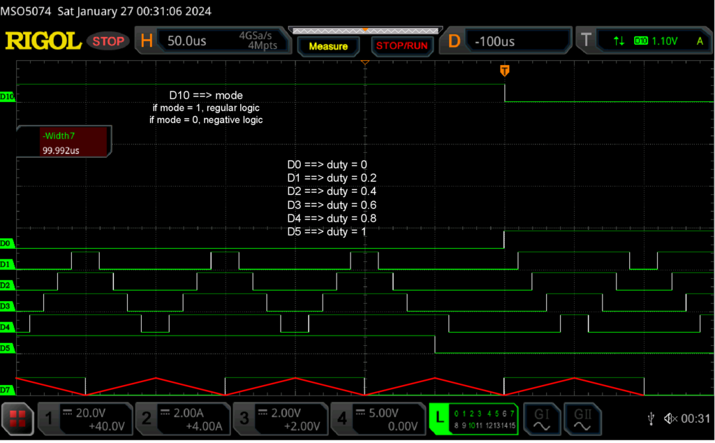
im working on a project where i need to change the PWM logic online and thats no problem, i just have to rewrite the EPwmxRegs.AQCTLA register. the problem is that i need this change to start at the time base counter when its zero, and at the moment the change occurs in between the max value and the zero when the counter is going down. this change is random and depends on the control calculations.
Hi Baldomero,
Using shadow-to-active loading should prevent any uncertainty in when settings are updated since shadow loading can be set to occur at a specific event/time - you can read some of the descriptions in the TRM section 15.6.4 AQCTLA and AQCTLB Shadow Mode Operations. I believe the default is to shadow load on CTR = 0, are you utilizing shadow loading for action qualifiers?
Best Regards,
Allison
yes, im using shadow loading for action qualifiers.
I made an example to ilustrate the problem. im using ePWM 1 to 3, A and B, and asigning them a duty cycle as shown in the image.
in the digital channel D7 i put a toggle signal so i can see when the counter of the ePWM reaches zero, and i even draw the counter. channel D10 show the compare logic, which i changed via an input. as you can se the problem is when i change the mode, the compare logic does not change at the zero counter, so right before the logic change, the pulse sequence does not end properly. i need it to end propoerly, so i need somehow write to the regiser when the counter reaches zero.
code:
------------- control loop ------------------
c = !c; // toggle value
// Write ePWMxA duty-cycles on ePMs
write_ePWMxA(1,0); // writes on ePWM1A a duty = 0
write_ePWMxA(2,.4);
write_ePWMxA(3,.8);
// Write ePWMxB duty-cycles on ePMs
// If using complementary EPMs then, duty-cycles are forced to be equal ePWMxB=ePWMxA
write_ePWMxB(1,.2);
write_ePWMxB(2,.6);
write_ePWMxB(3,1);
if(mode == 1){
EPwm1Regs.AQCTLA.bit.CAU = AQ_CLEAR; //
EPwm1Regs.AQCTLA.bit.CAD = AQ_SET;
EPwm1Regs.AQCTLA.bit.ZRO = AQ_SET;
EPwm1Regs.AQCTLB.bit.CBU = AQ_CLEAR; //
EPwm1Regs.AQCTLB.bit.CBD = AQ_SET;
EPwm1Regs.AQCTLB.bit.ZRO = AQ_SET;
EPwm2Regs.AQCTLA.bit.CAU = AQ_CLEAR; //
EPwm2Regs.AQCTLA.bit.CAD = AQ_SET;
EPwm2Regs.AQCTLA.bit.ZRO = AQ_SET;
EPwm2Regs.AQCTLB.bit.CBU = AQ_CLEAR; //
EPwm2Regs.AQCTLB.bit.CBD = AQ_SET;
EPwm2Regs.AQCTLB.bit.ZRO = AQ_SET;
EPwm3Regs.AQCTLA.bit.CAU = AQ_CLEAR; //
EPwm3Regs.AQCTLA.bit.CAD = AQ_SET;
EPwm3Regs.AQCTLA.bit.ZRO = AQ_SET;
EPwm3Regs.AQCTLB.bit.CBU = AQ_CLEAR; //
EPwm3Regs.AQCTLB.bit.CBD = AQ_SET;
EPwm3Regs.AQCTLB.bit.ZRO = AQ_SET;
}
// ------------------ negative logic --------------------
if(mode == 0){
EPwm1Regs.AQCTLA.bit.CAU = AQ_SET; //
EPwm1Regs.AQCTLA.bit.CAD = AQ_CLEAR;
EPwm1Regs.AQCTLA.bit.ZRO = AQ_CLEAR;
EPwm1Regs.AQCTLB.bit.CBU = AQ_SET; //
EPwm1Regs.AQCTLB.bit.CBD = AQ_CLEAR;
EPwm1Regs.AQCTLB.bit.ZRO = AQ_CLEAR;
EPwm2Regs.AQCTLA.bit.CAU = AQ_SET; //
EPwm2Regs.AQCTLA.bit.CAD = AQ_CLEAR;
EPwm2Regs.AQCTLA.bit.ZRO = AQ_CLEAR;
EPwm2Regs.AQCTLB.bit.CBU = AQ_SET; //
EPwm2Regs.AQCTLB.bit.CBD = AQ_CLEAR;
EPwm2Regs.AQCTLB.bit.ZRO = AQ_CLEAR;
EPwm3Regs.AQCTLA.bit.CAU = AQ_SET; //
EPwm3Regs.AQCTLA.bit.CAD = AQ_CLEAR;
EPwm3Regs.AQCTLA.bit.ZRO = AQ_CLEAR;
EPwm3Regs.AQCTLB.bit.CBU = AQ_SET; //
EPwm3Regs.AQCTLB.bit.CBD = AQ_CLEAR;
EPwm3Regs.AQCTLB.bit.ZRO = AQ_CLEAR;
}
write_ePWMxB(4,c);
write_ePWMxA(6,mode);
Hi Baldomero,
Thank you for the images and configurations. To clarify, are you saying that the issue is only with channel D4 of your oscilloscope image above when you describe an issue where it does not "end properly"? At what point in time is the mode being switched from mode 1 to mode 0 or vice versa? Also, what shadow loading settings are you using (e.g. shadow load on CTR = 0)?
Have you also tried using immediate load mode and seen a change in the behavior?
Best Regards,
Allison
The problem is with channel 0 to 5 (ePWM 1 to 3, A and B).
The expected pattern can be seen in the rectangle (1) and in rectangle (2) it can be seen that it does not finish it propoerly because the compare logic is changing in between the sampling time.
The mode was changed using the Debug feature of Code Composer Studio 11.0.0, with the "continuos refresh" option i can modify expressions when the code is already loaded on the Launchpad. The loading setting are shadow at CTR = 0, count mode up and down. timer interrupt at CTR = 0. i have not tried inmediate change because i need the loading occure at CTR = 0.
Since the change i made in the variable "mode" was wrote on the D10 channel, which is ePWM6A, the shadow mode will load that change at CTR = 0, because ePWM6 is also configurated like the other ePWMs. But if i have to say when the mode really changes i would say at the dashed line at (3) in the second image.
i would say that the change of logic happens at the instat marked by the dashed line (3), there the compare logic seems to change, and should be where the if condition code related to the "mode" variable is executed.
Hi Baldomero,
Did you attach 2 new images to your latest response above? I am unable to view them if you did - could you please resend them so I can get a better understanding of the issue with your current configuration? Or perhaps you can draw what it should look like when it is working as desired for your application.
Also, am I understanding correctly that you have an interrupt on CTR=0 to determine which mode the program is in and switch the appropriate AQ settings, and then these changes will shadow-to-active load on the next CTR=0 following the interrupt?
Best Regards,
Allison
In the first picture, as i said the problem was with the six ePWMs, 1 to 3 (A and B). in the rectangle (1) you can see the propoer pattern, and once i change the compare logic, the pattern does not end properly, as you can see in the rectangle (2). I made the change of "compare logic mode" using the Debug feature of Code Composer Studio 11.0.0, with the "continuos refresh" option. I can modify expressions when the code is already loaded on the Launchpad. So i changed the variable mode from 1 to 0. The pattern (2) should look like the pattern (1) before changing the compare logic, thats what im trying to do. But that is not happening because the change in compare logic does not happen at CTR = 0.
This change of "compare logic mode" as describe by the channel D10 does not happen at that instant. Because i needed a trigger signal for the osciloscope, i wrote the "mode" variable on the ePWM6A, this one is configurated with shadow register, so the loading happens at CTR = 0, but really the change of compare logic its happening before. Most certainly near the dashed line at (3), in the second image.
So the change of compare logic that im trying to write in the registers of EPwm1Regs.AQCTLA is happening at the line (3) and i need some how that this change to happen at CTR = 0.
Hi Baldomero,
Unfortunately I am still unable to view the images in this latest reply (I've read through your descriptions but they would make better sense were I able to see the rectangles (1), (2), etc. you are referring to). I tried to open the image sources but it looks like you are using a file sharing site to link the images and I cannot access them.
I am restricted from opening links from file sharing sites for security reasons. Apologies for the slight workaround, but could you please take screenshots of the images and insert the screenshots here instead of the source links?
Best Regards,
Allison
Baldomero,
Thanks for the images - I can understand the issue clearly. Can you share your PWM configurations/initialization (specifically for the D4 channel that is incorrectly changing).
It looks like all other PWM channels are changing at the correct time (or, rather, the AQ changes are shadow-to-active loaded when CTR=0 as expected) which means you should not see this AQ behavior on any of the channels until the CTR=0 event after (3). Does this issue occur every time you change the mode? Or is it only sometimes (dependent on the precise time or CTR value when you change it)?
Best Regards,
Allison
of course, D4 channel correspond to ePWM3B and is configurated like all ePWM. i have commented the definition of each value for better understanding.
---------------------- ePWM3 configuration ----------------------------------
EPwm3Regs.TBCTL.bit.HSPCLKDIV = TB_DIV1; // Clock ratio to SYSCLKOUT
EPwm3Regs.TBCTL.bit.CLKDIV = TB_DIV1; // #define TB_DIV1 0x0
EPwm3Regs.TBPRD = ePWMx_TMAX[pwm-1]; // Set timer period (Max Count), 5000 for 100e-6 time sample
EPwm3Regs.TBPHS.bit.TBPHS = ePWMx_PS[pwm-1]; // Phase Shift (initial counter value)
EPwm3Regs.TBCTR = 0x0000; // Clear counter
// Set Compare values
EPwm3Regs.CMPA.bit.CMPA = 0; // Set compare A value
EPwm3Regs.CMPB.bit.CMPB = 0; // Set Compare B value
// Setup counter mode
EPwm3Regs.TBCTL.bit.PHSDIR = readbit(ePWMx_PHSDIR,pwm-1); // Set Initial Count Direction
unsigned int pos = 2*(pwm-1);
unsigned int symm = readbit(ePWMx_SYMM,pos) + 2*readbit(ePWMx_SYMM,pos+1);
EPwm3Regs.TBCTL.bit.CTRMODE = symm; // Count up and down -- Symmetric PWM /\/\/
EPwm3Regs.TBCTL.bit.PHSEN = TB_ENABLE; // #define TB_ENABLE 0x1
EPwm3Regs.TBCTL.bit.PRDLD = TB_SHADOW; // #define TB_SHADOW 0x0
EPwm3Regs.TBCTL.bit.SYNCOSEL = TB_SYNC_IN; // #define TB_SYNC_IN 0x0
// Setup shadowing
EPwm3Regs.CMPCTL.bit.SHDWAMODE = CC_SHADOW; // #define CC_SHADOW 0x0
EPwm3Regs.CMPCTL.bit.SHDWBMODE = CC_SHADOW;
EPwm3Regs.CMPCTL.bit.LOADAMODE = CC_CTR_ZERO; // #define CC_CTR_ZERO 0x0
EPwm3Regs.CMPCTL.bit.LOADBMODE = CC_CTR_ZERO;
// PWM Logic
//************************
// EPWM3A Positive
EPwm3Regs.AQCTLA.bit.CAU = AQ_CLEAR; // #define AQ_CLEAR 0x1
EPwm3Regs.AQCTLA.bit.CAD = AQ_SET; // #define AQ_SET 0x2
EPwm3Regs.AQCTLA.bit.ZRO = AQ_SET;
// EPWM3B Positive
EPwm3Regs.AQCTLB.bit.CBU = AQ_CLEAR;
EPwm3Regs.AQCTLB.bit.CBD = AQ_SET;
EPwm3Regs.AQCTLB.bit.ZRO = AQ_SET;
// Timer Interrupt
EPwm3Regs.ETSEL.bit.INTSEL = ET_CTR_ZERO; //#define ET_CTR_ZERO 0x1
EPwm3Regs.ETSEL.bit.INTEN = 1; //
EPwm3Regs.ETPS.bit.INTPRD = ET_1ST; // #define ET_1ST 0x1
EPwm3Regs.DBCTL.bit.OUT_MODE = DB_DISABLE; // #define DB_DISABLE 0x0
---------------------------------------------------------------------- ---
i dont think the behavior of the D4 channel is wrong, rather correct for the situation im experiencing. Because of shadow loading, it knows that at a deternuined moment of the CAU it has to do some action, which previously was "Clear", but since im changing the logic compare near the dashed line (3), now the action is "Set", so it stay the same. And then since the logic is negative, at CAD now it does a "Clear" rather than a "Set".
I've run this test multiple times and this issue occur every time i change the mode.
Hi Baldomero,
Thanks for sending the configurations. My understanding is that if you are changing the registers at (3) and have shadow loading on CTR = 0, the change should not be applied until the end of (2).
Can I ask how you are determining when you are changing the action qualifiers? Could you do this in an ISR instead of using the CCS expressions window so that you can debug (e.g. you can toggle a GPIO in the ISR when you change your AQs to scope out where exactly the change is occurring in regard to the CTR value.
Best Regards,
Allison
Hi Allison,
The Action qualifiers are defined by a duty cycle which remains constat through all this test, as defined in the image (1). the code i use go as following
-------code-------------
// Write ePWMxA duty-cycles on ePWMs
write_ePWMxA(1,0); // writes on ePWM1A a duty = 0
write_ePWMxA(2,0.4);
write_ePWMxA(3,0.8);
// Write ePWMxB duty-cycles on ePWMs
write_ePWMxB(1,0.2);
write_ePWMxB(2,0.6);
write_ePWMxB(3,1);
-----------------------------------------------
// write ePWMxA function
void write_ePWMxA(unsigned int pwm, float d)
{
unsigned int out =0;
if (d<0)
d=0;
if (d>1)
d=1;
if (pwm<13){
ePWMAx_duty_cycle[pwm-1] = d;
out = (unsigned int)(d*ePWMx_TMAX[pwm-1]);
if (pwm==1)
EPwm1Regs.CMPA.bit.CMPA = out; // adjust duty for output EPWM1A
if (pwm==2)
EPwm2Regs.CMPA.bit.CMPA = out; // adjust duty for output EPWM2A
if (pwm==3)
EPwm3Regs.CMPA.bit.CMPA = out; // adjust duty for output EPWM3A
if (pwm==4)
EPwm4Regs.CMPA.bit.CMPA = out; // adjust duty for output EPWM4A
if (pwm==5)
EPwm5Regs.CMPA.bit.CMPA = out; // adjust duty for output EPWM5A
if (pwm==6)
EPwm6Regs.CMPA.bit.CMPA = out; // adjust duty for output EPWM6A
if (pwm==7)
EPwm7Regs.CMPA.bit.CMPA = out; // adjust duty for output EPWM7A
if (pwm==8)
EPwm8Regs.CMPA.bit.CMPA = out; // adjust duty for output EPWM8A
if (pwm==9)
EPwm9Regs.CMPA.bit.CMPA = out; // adjust duty for output EPWM9A
if (pwm==10)
EPwm10Regs.CMPA.bit.CMPA = out; // adjust duty for output EPWM10A
if (pwm==11)
EPwm11Regs.CMPA.bit.CMPA = out; // adjust duty for output EPWM11A
if (pwm==12)
EPwm12Regs.CMPA.bit.CMPA = out; // adjust duty for output EPWM12A
}
}
------------------ end of code ---------------------
I've been working on Code Composer for approximately a month, so I'm still learning about this software. What is an ISR?
Hi Baldomero,
Glad to see you are new and learning the software!
To learn more about interrupts and ISR's a good place to go would be the device TRM section 3.4 Peripheral Interrupts.
Since you are still learning the software, I also have some other suggestions in terms of resources that may be very helpful:
I'd highly recommend taking a look at some/all of these to help with your learning and any other related questions. Let me know if you are able to understand ISRs - they are commonly used in out C2000Ware examples and C2000 Academy labs as well if you are needing to see references of how they are used
Best Regards,
Allison