This thread has been locked.

If you have a related question, please click the "Ask a related question" button in the top right corner. The newly created question will be automatically linked to this question.

SM320F28335-EP: ePWM channel crosstalk.....

Part Number: SM320F28335-EP

I am using epwm 1,2,3 for a motor control bridge, 4 is for a test signal that i can configure for a number of feedback signals but is primarily to indicate motor speed, 5 is a clock for a board level device and 6 is for ADC conversions.  My problem is that when i include pwm 4 into the build my motor currents have an intermittent spike that is not part of the sinusoidal currents that i expect to see but if i exclude pwm 4 they look correct.  It might be periodic it is hard to tell on the scope.  I could look at the motor pwm signals to try and see what is going on but they are not readily available and would need to bring them out.  I understand the daisy chain idea but it doesnt seem like that would be an issue.  See what you think and thanks!

My question 
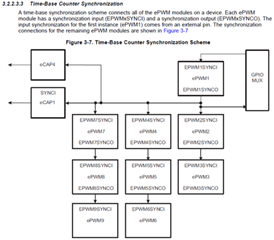
is - is there something that i might be doing with pwm 4 that can affect 1,2,3 ??

  • Hi Mark,

    Is there any relationship between the EPWM4 and EPWMs 1/2/3 within software (e.g. calculations or other items that are dependent) that could affect the behavior of EPWMs 1/2/3? Or do you suspect this is fully hardware-related? No immediate thought jumps out as to why this would occur if you're just adding one EPWM module, but let me also consult another expert when we are back in the office tomorrow and update you then.

    Best Regards,

    Allison

  • Thanks for looking into it, i think i figured out the fix although am not sure why.  For epwm 1,2,3 i was using the complement pins but for epwm 4 i was not and i set the gpio function registers to match.  In the epwm 4 initialization I was loading the 4a and 4b registers and after taking the complement inti out it seems like 1,2,3 are functioning properly again.  Hopefully this helps.  Thanks

  • Hi Mark,

    Glad to hear it is resolved! Could you explain what you mean by "complement" pins?

    Best Regards,

    Allison

  • The pwm device has A and B signals, i am referring to the B signal as the complement.  For the motor signals to our bridge we use A and B but for the signal i am describing here we are using only the 4A signal.  As I mentioned i initialized the 4A and 4B pwm registers but set only the 4A pin as pwm and left 4B as gpio but i guess that was enough to mess something up with the pwm 1,2,3 outputs although i am not sure what.  I hope this helps.  It seems like there is either something I am not aware of or some kind of error but I might be wrong.  Thanks.

  • Hi Mark,

    Thanks for the explanation. Let me look into if we have any known information on this over the next 2-3 days to see if it can help shed some light. 

    Best Regards,

    Allison

  • Hi Mark,

    It should still be fine to use these 2 GPIO pins independently (as in, use EPWMA pin for EPWM and EPWMB pin as a normal GPIO)- I'm double checking with design on this to be certain. Can I ask what you are doing on the GPIO? Perhaps something else is occurring with your use case.

    Best Regards,

    Allison

  • Good question but i did not use it for anything.  Thanks

  • Hi Mark,

    Okay understood. I will let you know when I hear back from design on this or have other speculations.

    Best Regards,

    Allison

  • Hi Mark,

    Sorry for the late response. The design team does not see any logic to prove the dependency described here, so I'm going to go ahead and close this thread. Feel free to start a new thread if you run into more issues.

    Best Regards,

    Allison