TMS320F2800157: DRV8353RS CUSTOM POWER BOARD INTERFACING ISSUE

Part Number: TMS320F2800157
Other Parts Discussed in Thread: DRV8353RS-EVM

Hello TI,

We are connecting our custom MOSFET power board with DRV8353RS Development board.

Trying to run the 24V BLDC motor by DRV8353RS board with our custom power board,
for interfacing we have removed the MOSFETS(Q1Q4,Q3Q6,Q2Q5) ,Shunt resistors(R14,R15,R16), and R55,R56,R57 also removed.

GHA,GLA,TP3 and GHB,GLB,TP2 and GHC,GLC,TP1 connections are taken out from DRV and connected with custom MOSFET power board.
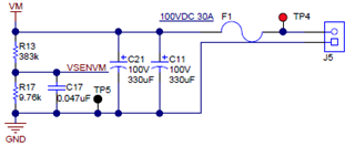
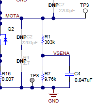
DRV8353RS Development board voltage divider Resistor network only using for phase voltage measurement
for phase current measurement CURSEN_TYPE_INLINE_HALL (hall sensor) used and its available in Custom mosfet power board.

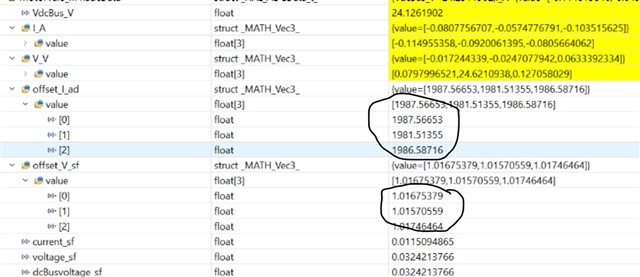
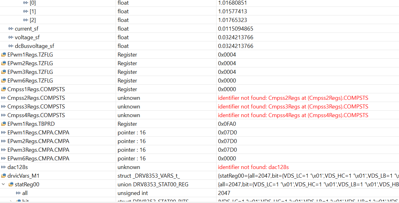
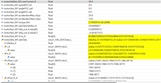
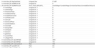
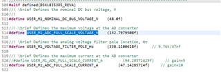
when run the code at Build level 1 Current offset measurement showing around 2000 and its expected one, for voltage offset measurement instead of 0.49 its showing 1.01,and voltage offset error occurred and Fault LED Getting ON while run the code.


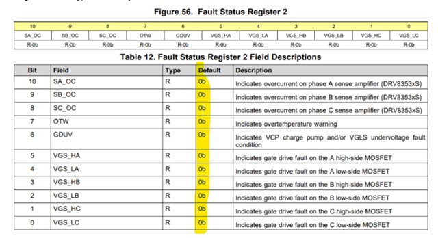
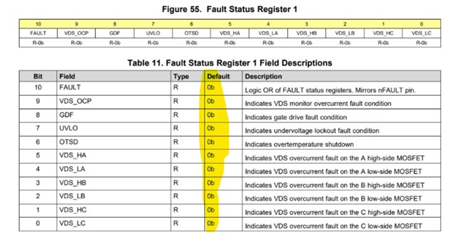
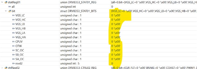
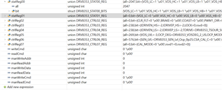
In SPI Failure status register 1 and 2 also checked, there is no failure bit has set.
what would be the issue, reference images also attached here.

Thanks in Advance.

  • Hello,

    Referring to the DRV8353RS-EVM, you can see that there are numerous signals connected from the DRV8353RX portion of the schematic to the HALF-BRIDGES & SENSE portion of the schematic. It sounds like your intent is to replace this portion with a custom implementation. However, you did not mention the SHx, SPx, SNx, or VSENx signals. Please ensure those are either connected to valid locations on your custom board.

    If this resolves the issue, please indicate so. If not, I'll attempt to continue the debug process!

    Regards,
    Jason Osborn

  • Dear Jason Osborn

    Thank you for you valuable Answers.

    Instead of SHX we used TPX (Test points) from DRV, and connected to our custom board
    between HIGH SIDE SOURCE and LOW SIDE DRAIN Mosfet points.

    We are using hall sensor (CURSEN_TYPE_INLINE_HALL) for current measurement, not shunt type measurement
    For that SPX, SNX not connected to our custom board, HALL Sensor Output are directly connected to F2800157 Microcontroller pins.

    For Voltage measurement VSENX signals are used and connected to F2800157 Microcontroller pins.

    Thanks in Advance.

  • Hi,

    We know that the offset calibration routine is working OK since your current offsets are correct. There's some issue with your phase voltage sensing however.

    Can you confirm the ADC signals used are correct and sensing the phase voltages properly? F280015x device is not supported by UMCL, so you must have ported the software. Note, that if using AGPIO signals you must configure them in analog mode within software.

    Best,

    Kevin

  • Dear Kevin Allen,

    We are applying 24VDC for small BLDC Motor, and its showing Proper voltage (24.1V), please refer the attachment.

    we have converted the code from 25C Controller to 157, and this code verified with DRV8353RS driver with same 24V BLDC Motor and its working fine.

    So, the same GPIO and AGPIO pin configurations followed for our custom board interfacing also,

    when we start to run the code debug option fault LED Getting ON.

    Thanks in Advance

    Regards

    Murali Subramani

  • Hi Murali,

    We are applying 24VDC for small BLDC Motor, and its showing Proper voltage (24.1V), please refer the attachment.

    OK, you have verified the ADC sampling is correct for all 3 motor phases then (i.e. when you sense 24V)? Just to confirm.

    we have converted the code from 25C Controller to 157, and this code verified with DRV8353RS driver with same 24V BLDC Motor and its working fine.

    You are meaning it worked with the F28002x device and the exact same DRV8353RS custom hardware? Or something else?

    when we start to run the code debug option fault LED Getting ON.

    What condition in the code is causing the fault LED to turn ON? Or is this a fault signal from the DRV device?

    It would be nice to be able to run the motor in open-loop (Build Level #2) and plot the phase voltage sensing values to see the shape / values.

    Best,

    Kevin

  • Q - OK, you have verified the ADC sampling is correct for all 3 motor phases then (i.e. when you sense 24V)? Just to confirm.

    Ans - We are checking at build level #1, without connecting motor, Hardware side 0.6 V expected voltage we are getting in all three ADC Channel when 24V  sense. but in Software its showing Offset error.

    Q - You are meaning it worked with the F28002x device and the exact same DRV8353RS custom hardware? Or something else?

    Ans - DRV8353RS TI Hardware.

    Q - What condition in the code is causing the fault LED to turn ON? Or is this a fault signal from the DRV device?

    Ans - Fault LED of DRV device on TI board.

    Q - It would be nice to be able to run the motor in open-loop (Build Level #2) and plot the phase voltage sensing values to see the shape / values.

    Ans - Voltage Offset error bit is set. Complete screen shot is attached here.

  • Hi Murali,

    Can you provide a picture of your hardware set-up with the custom MOSFET board? Maybe there's something I'm misunderstanding about your set-up.

    Is there any difference in the voltage divider / circuit for phase voltage sensing and DC_bus voltage sensing? They should be the same for this software.

    Did you change 'USER_M1_ADC_FULL_SCALE_VOLTAGE_V' in the software?

    //! \brief Defines the maximum voltage at the AD converter
    #define USER_M1_ADC_FULL_SCALE_VOLTAGE_V    (132.7979508f)

    Verify 50% duty cycle PWMs during offset calculation process.

    Best,

    Kevin

  • Hi Allen,

    Allen - Can you provide a picture of your hardware set-up with the custom MOSFET board? Maybe there's something I'm misunderstanding about your set-up.

    Murali - Due to Confidentiality Iam not able to share the picture here, But I could clarify my connections. MOSFET and Current sensing circuits only we are using in our custom board for interfacing the DRV8353RS.

    Allen - Is there any difference in the voltage divider / circuit for phase voltage sensing and DC bus voltage sensing? They should be the same for this software.

    Murali - NO Difference, Same Voltage divider network which is currently available in DRV8353RS Board only we are using and connected to microcontroller pins.

    Allen - Did you change 'USER_M1_ADC_FULL_SCALE_VOLTAGE_V' in the software?

    Murali - I have not change this MACROS, Reference screen shot attached here,


              with these values, we have connected the motor with DRV8353RS Board and motor was running.

              with this same values only we are connecting our custom MOSFET Power board.

    Thanks in Advance.

  • Hi Murali,

    Murali - Due to Confidentiality Iam not able to share the picture here, But I could clarify my connections. MOSFET and Current sensing circuits only we are using in our custom board for interfacing the DRV8353RS.

    Understand, alternatively you could send pictures directly to me using the E2E private messenger.

    Murali - NO Difference, Same Voltage divider network which is currently available in DRV8353RS Board only we are using and connected to microcontroller pins.

    What do you mean by "only we are using and connected to microcontroller pins"? How does this differ from the DRV8353RS-EVM board?

    Maybe probing the Phase voltage sensing ADC pins during the offset calibration process would provide some indication of the issue. This could be compared when running with the DRV8353RS-EVM board as well.

    Best,

    Kevin