


Other Parts Discussed in Thread: ADS7038
Hi,
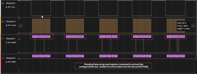
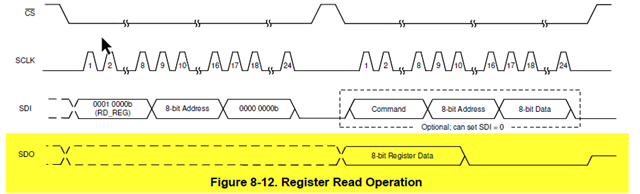
I've connected TMS320F280039C control card with ADS7038 IC, According to the data sheet I'm sending the Configuration data and reading back weather the data is written correctly or not but I'm unable to receive any data from the ADS7038 Module.
Configuration are as follows:
> Baudrate : 1Mhz
> bit size : 8
> Using FIFO
> SPI Mode 0
> Controller Mode
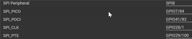
> PinMux:
Code I'm sending is attached below:
void ADC_ExternalInit( void )
{
uint16_t i = 0;
static uint16_t tmp_Error_uint16_t = FALSE;
/* Write the configuration of the external ADC, instead of the last entry, that is activating the auto sequence mode. */
for ( i=0 ;i < ( ADC_Sys_Ex_StartupConfig_Length_u16 - 1u );i++ )
{
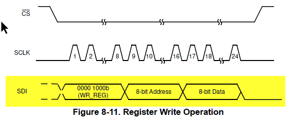
/* Write three times eight bit = 24-Bits in total. */
SPI_transmitNBytes(SPIB_BASE,(uint16_t *)&ADC_Sys_Ex_StartupConfig_a16[i*3], (uint16_t)3, (uint16_t)0);
/* Clear of fifo pointer is needed, otherwise the function SPI_writeDataBlocking will not work next time. */
SPI_clearFIFOPointer();
}
/* Readback the registers hat has been previously written to ensure the correct operation. */
for ( i=0;i<ADC_Sys_Ex_StartupConfigReadback_Length_u16;i++ )
{
/* Write three times eight bit = 24-Bits in total. */
SPI_transmitNBytes(SPIB_BASE,(uint16_t *)&ADC_Sys_Ex_StartupConfigReadback_a16[i*3], 3, 0);
if ( i >= 1u )
{
if ( SPI_M_READ_BUFFER != ADC_Sys_Ex_StartupConfig_a16[((i-1u)*3u)+2u] )
{
tmp_Error_uint16_t = TRUE;
}
}
SPI_clearFIFOPointer();
}
/* Check if an error is present during the external ADC setup. */
if ( tmp_Error_uint16_t == ( uint16_t ) TRUE )
{
ADC_Sys_Ex_ADCInit_uint16_t = FALSE;
}
else
{
ADC_Sys_Ex_ADCInit_uint16_t = TRUE;
/* Activate the auto sequence mode at the end of the init phase. */
SPI_transmitNBytes(SPIB_BASE,(uint16_t *)&ADC_Sys_Ex_StartupConfig_a16[(ADC_Sys_Ex_StartupConfig_Length_u16-1u)*3u], 3, 0);
/* Clear of fifo pointer is needed, otherwise the function SPI_writeDataBlocking will not work next time. */
SPI_clearFIFOPointer();
}
/***********************************************************************************/
extern void SPI_clearFIFOPointer ( void ) {
/* TX FIFO */
/* Write 0 to reset the FIFO pointer to zero, and hold in reset.*/
HWREGH(SPIB_BASE + SPI_FFTX_SPIRST) = SPI_D_FIFO_RESET;
/* RX FIFO */
/* Write 0 to reset the FIFO pointer to zero, and hold in reset.*/
HWREGH(SPIB_BASE + SPI_FFRX_RXFIFORESET) = SPI_D_FIFO_RESET;
/* Restart FIFO, first start with Rx - FIFO */
/* Release receive FIFO from reset. */
HWREGH(SPIB_BASE + SPI_FFRX_RXFIFORESET) = SPI_D_FIFO_RELEASE;
/* Release transmit FIFO from reset. */
HWREGH(SPIB_BASE + SPI_FFTX_SPIRST) = SPI_D_FIFO_RELEASE;
}
/***********************************************************************************/
static const uint16_t ADC_Sys_Ex_StartupConfig_a16 [] = {
ADC_EXT_WR_REG,0x10,0x00, /* Disable a current on going conversion. */
ADC_EXT_WR_REG,0x01,0x00, /* Reset the configuration at startupd. */
ADC_EXT_WR_REG,0x02,0x10, /* Append a 4-bit channel ID to the measured data. */
ADC_EXT_WR_REG,0x03,0x00, /* Oversampling is deactivated. */
ADC_EXT_WR_REG,0x04,0x00, /* 1 MHz sample rate + Auto sequence mode. */
ADC_EXT_WR_REG,0x05,0x00, /* All channels are configured as analog input. */
ADC_EXT_WR_REG,0x12,0x0F, /* CH0, CH1, CH2 and CH3 are enabled for the auto sequence mode. */
ADC_EXT_WR_REG,0x10,0x11, /* Start the auto sequence mode. */
};
static const uint16_t ADC_Sys_Ex_StartupConfigReadback_a16 [] = {
ADC_EXT_RD_REG,0x10,0x00, /* Disable a current on going conversion. */
ADC_EXT_RD_REG,0x01,0x00, /* Reset the configuration at startupd. */
ADC_EXT_RD_REG,0x02,0x00, /* Append a 4-bit channel ID to the measured data. */
ADC_EXT_RD_REG,0x03,0x00, /* Oversampling is deactivated. */
ADC_EXT_RD_REG,0x04,0x00, /* 1 MHz sample rate + Auto sequence mode. */
ADC_EXT_RD_REG,0x05,0x00, /* All channels are configured as analog input. */
ADC_EXT_RD_REG,0x12,0x00, /* CH0, CH1, CH2 and CH3 are enabled for the auto sequence mode. */
0x00,0x00,0x00 /* One additional row with dummy data to read out the last register. */
};
static uint16_t ADC_Sys_Ex_StartupConfig_Length_u16 = 8u;
static uint16_t ADC_Sys_Ex_StartupConfigReadback_Length_u16 = 8u;
/***********************************************************************************/
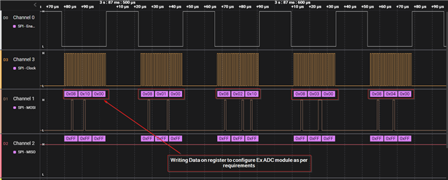
Output snippets are attached Below:
Note:
> ADS7038 is working on 3.3 voltage.
I've certain doubts:
1. Does ADS7038 is by default in Peripheral mode?
2. Do I need to enable Hardware write/read protection in ADS7038? if yes, how do I do that?
Please let me know where the problem could be and how can I resolve it.
Thank you,
regards,
Tejas Udge
