TMS320F28375S: Issue with Source File Availability Post Bootloader Jump on TMS320F28375S

Part Number: TMS320F28375S
Other Parts Discussed in Thread: C2000WARE

Hello E2E Community,

I am currently working on a bootloader-to-application jump scenario with the TMS320F28375S controller. My bootloader is located in the FLASHA, B, C, and D sections (first 4 sections of 8k words each starting from 0x80000), with some space left unused for future use. The application is allocated from FLASHE to J (next 6 sections of 32k words each starting from 0x88000), again with some space intentionally left free.

The process for jumping from the bootloader to the application is as follows:

// Disable global interrupts
DINT;
IER = 0x0000;
IFR = 0x0000;
asm (" LB 0x088000");

However, when the LB instruction is executed, the system hangs and CCS displays the following error message: "No source available for '_system_post_cinit' at [memory address]". I have also attempted to jump directly to the location where _c_init100 is detailed in the .map file, but I encounter the same issue.

Attached is a screenshot of the error message for reference.

Can anyone advise what might be going wrong? Is there a problem with my jump instruction, or could it be an issue with the source lookup configuration in CCS? Any insights or suggestions would be greatly appreciated.

Thank you for your assistance!
Regards
Muzammil Qureshi

  • Hi Muzammil,

    I'll need some more time to look into this, will get back to you within the next day.

    Thanks and regards,

    Charles

  • Hi Charles,

    Thank you for your response and for agreeing to look further into this.

    I'm writing to give you more context about the issue I'm facing with jumping to an application from an RTOS task. The jump works fine before the RTOS is initialized, during the setup phase before entering the main loop. However, when I try to jump from within the loop, it doesn't work.

    I've attempted the jump both by using assembly code and with a function pointer, but both methods lead to the system hanging. The disassembly shows that the code gets stuck at ESTOP0 every time.

    I'm also unsure about how to properly set up the vector table and the stack pointer for this transition. Should I be jumping to the location from where my application starts i.e. 0x88000 or _c_init00 (0x8d40f as per .map file)? And how can I make sure the vector table and stack pointer are correctly defined for the jump from the bootloader or RTOS to the application?

    I've seen several threads about similar issues, but I'm having a hard time understanding them. Any insights or suggestions you could provide would be immensely helpful, especially any specific considerations for the vector table, stack pointer setup, and determining the right jump destination within an RTOS context.

    Thanks again for your help.

    Best regards,

    Muzammil

  • Hi Muzammil,

    For the given process for jumping from the bootloader to the application above, did you initialize the flash control registers prior to branching to the entry address?

    From the bootloader you should be aiming to jump to the application entry-point address (0x88000). Can you share your map file if possible? 

    Thanks and regards,

    Charles

  • Hello Charles,

    For the given process for jumping from the bootloader to the application above, did you initialize the flash control registers prior to branching to the entry address?

    I have initialised the flash after the Device_init() function.

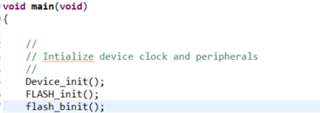
    Below I have shown how I have initialised the flash.   

    void FLASH_init(){
        //
        // myFMC0 Initialization
        // 
        //
        // Set the bank power up delay so that the bank will power up properly.
        //
        Flash_setBankPowerUpDelay(myFMC0_BASE, 0x14);
        //
        // This function sets the fallback power mode of the flash bank specified by
        // the bank parameter. The power mode is specified by the powerMode
        // parameter
        //
        
        //
        // Set available banks to active power mode
        // 
        Flash_setBankPowerMode(myFMC0_BASE, FLASH_BANK, FLASH_BANK_PWR_ACTIVE);
        //
        // Sets the fallback power mode of the charge pump.
        //
        // Set pump power mode to active
        //
        Flash_setPumpPowerMode(myFMC0_BASE, FLASH_PUMP_PWR_ACTIVE);
        //
        // Disable cache and prefetch mechanism before changing wait states
        //
        Flash_disableCache(myFMC0_BASE);
        Flash_disablePrefetch(myFMC0_BASE);
        //
        // This function sets the number of wait states for a flash read access. The
        // waitstates parameter is a number between 0 and 15. It is important
        // to look at your device's datasheet for information about what the required
        // minimum flash wait-state is for your selected SYSCLK frequency.
        //
        // By default the wait state amount is configured to the maximum 15. 
        //
        // Set flash wait states
        //
        Flash_setWaitstates(myFMC0_BASE, myFMC0_WAITSTATES); 
        //
        // Enable prefetch
        //
        Flash_enablePrefetch(myFMC0_BASE);
        //
        // Enable cache
        //
        Flash_enableCache(myFMC0_BASE);
        //
        // Enables flash error correction code (ECC) protection.
        //
        Flash_enableECC(myFMC0_ECCBASE);
        //
        // Sets the single bit error threshold. Valid ranges are from 0-65535.
        //
        Flash_setErrorThreshold(myFMC0_ECCBASE, myFMC0_ERRORTHRESHOLD);
        //
        // Force a pipeline flush to ensure that the write to the last register
        // configured occurs before returning.
        //
        FLASH_DELAY_CONFIG;
    }
    
    HAL_ApiState flash_binit(void)
    {
        HAL_ApiState internal_flash_api_init_status = HAL_SUCCESS;
        /**** Flash Initialize need to done both bank .this MCU has two flash bank only  ****/
        Flash_initModule(myFMC0_BASE, myFMC0_ECCBASE, myFMC0_WAITSTATES);
        // Enable writing to the EALLOW protected registers
        EALLOW;
        //
        // oReturnCheck is used to store the status of the flash API
        //
        Fapi_StatusType oReturnCheck;
        //
        // Initialize the flash API
        //
        oReturnCheck = Fapi_initializeAPI(F021_CPU0_W0_BASE_ADDRESS, 200);
        //
        // Check the status of the flash API for an error
        //
        if(oReturnCheck != Fapi_Status_Success)
        {
            internal_flash_api_init_status = HAL_FAIL;
            return internal_flash_api_init_status;
        }
        //
        // Initialize the Flash Memory Controller (FMC) and banks for an erase or
        // program command
        //
        oReturnCheck = Fapi_setActiveFlashBank(Fapi_FlashBank0);
        //
        // Check the status of the flash API for an error
        //
        if(oReturnCheck != Fapi_Status_Success)
        {
            internal_flash_api_init_status = HAL_FAIL;
        }
    
        // oReturnCheck = Fapi_setActiveFlashBank(Fapi_FlashBank1);
        //
        // Check the status of the flash API for an error
        //
    //    if(oReturnCheck != Fapi_Status_Success)
    //    {
    //        internal_flash_api_init_status = HAL_FAIL;
    //    }
        //
        // Disable writing to the EALLOW protected registers
        //
        EDIS;
    
        return internal_flash_api_init_status;
    }
    

    Can you share your map file if possible? 

    The below file is .map file of my application.

    0714.motor-controller-ti.zip

    I had mistakenly told you wrong address of _c_int00 in my previous question, actually it is 0x8b40f.

    should i do any changes in my project settings?

    can you please tell me the procedure to jump from bootloader code to application.

    thanks and regards

    Muzammil

  • Muzammil,

    For your project settings, is it possible to add a codestart for the Codestart_branch asm file?

    Then, the way to jump from bootloader code to application is through using the "return" function. Have you looked at the F2837xS SCI Bootloader project as a basis for your kernel? And does using this function make a difference?

    Thanks,

    Charles

  • Hi Charles,

    Thank you for your suggestions and for guiding me through this process. I wanted to clarify a few things to ensure I'm on the right track. Firstly, when you mentioned adding a codestart for the Codestart_branch.asm file, I wanted to confirm what specific additions you are referring to, as I have already included the F2837xS_CodeStartBranch.asm file in my project. Are there specific modifications or configurations within this file that I need to adjust or verify?

    Regarding the use of the "return" function from the SCI bootloader kernel, However, I am using CAN for Bootloader operation, I know that there is DCAN Bootloader also same as SCI bootloader. I understand this is part of the standard procedure in the SCI bootloader project typically located in the boot_rom folder of the libraries. Integrating the DCAN bootloader's return function would require significant changes to my existing project structure and logic.

    Additionally, I'm facing challenges with jumping to an application from within an RTOS task. The jump works fine before the RTOS is initialized, during the setup phase before entering the main loop. However, it doesn't work when I try to jump from within the loop. Could you provide some insights on what might be causing this issue and how it could be resolved? Also, how can I ensure that the vector table and stack pointer are correctly defined for the jump from the bootloader or RTOS to the application? Any specific guidelines or checks that I should follow would be greatly appreciated.

    Thanks again for your help, and I look forward to your advice on how best to proceed with these adjustments.

    Best regards,

    Muzammil

  • Hi Muzammil,

    After reading over your post, I'll need some more information from my team on how RTOS interacts with the CAN Flash kernel. With an RTOS, it is true that you cannot jump straight to an application due to the scheduler of the RTOS. Will update you with the latest when available. 

    Thanks and regards,

    Charles

  • Hi Muzammil,

    To clarify, are you using a bootloader with RTOS, or are these for separate use cases? Are you able to see at which point the code hits ESTOP?

    In general, when switching to a new application from a FreeRTOS application, the steps would be to 1) Stop tick timer 2) Reset timer and peripheral interrupts to clear existing flags 3) Disable global interrupts 4) Jump to new application entry point

    The vector table (re)initialization would be done as part of the second application, following which interrupts can be re-enabled

    Thanks,

    Arnav

  • Hi Arnav,

    I followed your advice, and I'm happy to report that I'm now able to jump correctly to the application, so thank you for that guidance! However, my code is not working because of some problem.

    When I program the application using the CCS plugin and run only application, everything works as expected, but when I flash the binary file of the application with bootloader code using flash_api, the code doesn't function properly. Additionally, I've noticed a discrepancy between the data in the .bin file of the application and what I see in the flash portion of the memory browser after debugging with CCS. The .bin file contains more data than is shown in the CCS memory browser.

    I'm wondering if the .bin file is generated considering all memory regions, including RAM. Could this be why there's more data in the .bin file than in the flash portion viewed in the memory browser? If this is the case, how can I differentiate which data should be stored in which location?

    For context, my bootloader is located in the FLASHA, B, C, and D sections (first 4 sections of 8k words each starting from 0x80000), with some space left unused for future use. The application is allocated from FLASHE to J (next 6 sections of 32k words each starting from 0x88000), again with some space intentionally left free. Additionally, some RAM portions are also used in both projects.

    Could this be related to how I'm flashing the binary file? Is there a specific method or procedure I should follow to ensure the binary data is correctly written to the controller's flash memory?

    here I am attaching the command file of both the projects.

    7180.cmd.zip

    Thanks for your help!

    Best regards,

    Muzammil

  • Hi Muzammil,

    Will review the attached command files before providing further input.

    Thanks and regards,

    Charles

  • Hi Muzammil,

    After reviewing, I'll need some further input. How is it that you are generating the bin file? 
    I'll also need the map files for both application and bootloader.

    Thanks,

    Charles

  • Hi Charles,

    Thank you for your follow-up. Regarding the generation of the binary file, Here's the method I use within Code Composer Studio (CCS):

    1. I right-click on the project in the 'Project Explorer'.
    2. I navigate to Properties -> C2000 Hex Utility -> Output Format Options.
    3. In the output format options, I select Binary (--binary, -b) to generate the .bin file.

    This process is how I've been creating the binary files that I use for flashing.

    I am attaching the map files for both the application and bootloader below.

    map files.zip

    please note that 'mc-bl-app' is of bootloader project and 'motor-controller-ti' is of application.

    Please let me know if there's anything else you need or further details that might assist in resolving the issues with flashing the binary file correctly.

    Thanks again for your assistance.

    Best regards

    Muzammil

  • Hi Muzammil,

    Can you generate the text file for the bootloader as specified in the Serial Flash Programming of C2000 Microcontrollers application note?

    The post-build step is as follows: "${CG_TOOL_HEX}" "${BuildArtifactFileName}" -boot -sci8 -a -o "${BuildArtifactFileBaseName}.txt"

    For the flash build configuration of your projects, you can add this post-build step which will generate the text file for flashing the device. 

    Thanks and regards,
    Charles

  • Hi Charles,

    I appreciate your help with the text file generation for my bootloader. my file is generated as shown below.

    8004.motor-controller-ti.zip

    However, I'm encountering some challenges with the actual flashing process, and I hope you can provide some guidance. My application starts at 0x88000, but the text file generated doesn't specify memory addresses, making it unclear which data should be flashed to which location. This is crucial as I am using a custom bootloader that receives data via CAN and uses a flash API to program it into the microcontroller. Currently, my approach has been to start flashing the data in 8-byte chunks from 0x88000 onwards until the end of the data. I am unsure if this method is correct or if there's a more recommended technique to ensure proper programming.

    Additionally, I've observed a discrepancy between the data size in the .bin (or equivalent .txt) file and what is shown in the flash portion of the CCS memory browser after debugging. The .bin file appears to contain more data than the CCS memory browser displays. Also, how should I handle the RAM portion involved in this process?

    MC_Raw.zip

    the above file is generated from memory browser of CCS after debugging my application project. you can see in file that how the data is stored. there is some space left as FLASHE is not filled fully(you can see in cmd file of app project). i also want the same. also there is some RAM portion is used which i have not saved while generating this file.

    after comparing the above file of memory browser and the txt file which i have generated, i can see that the data is not in same manner in both. also the data txt file is 8 bits and actually it is 16 bits. 

    Could you advise on how to correctly interpret and flash the data from this text file using a custom bootloader? Any insights or recommended practices would be immensely helpful.

    Thank you for your assistance.

    Best regards, Muzammil

  • Hi Charles,

    Thank you for your guidance so far. After a closer examination of the .txt file, I’ve decoded some of its structure. The first two data bytes represent the data length, and the following four bytes denote the address at which the data should be stored. This has clarified a lot but has also led to a couple of significant challenges:

    1. Decoding Complexity: The process of decoding this format from the text file is proving to be quite cumbersome. Removing the first six bytes to parse the remaining data and then correctly storing this data in flash presents a practical challenge, especially when automating this process for a custom bootloader. The need to manually adjust for these initial bytes and accurately parse the subsequent data adds complexity to the implementation.

    2. Data Breaks on FFFF: Another issue arises with data sequences containing FFFF. It appears that whenever FFFF is encountered, it acts as a delimiter or breakpoint, which disrupts the continuous flow of data. If I'm correct in my understanding, the data following FFFF is then considered as a new address, which complicates the parsing logic significantly, especially for longer and continuous blocks of data.

    Given these issues, could you advise on a more efficient method or tool that might simplify this process, particularly one that could handle the peculiarities of data delimitation and address recognition more gracefully? Any insights or suggestions on how to tackle these specific challenges within the context of a custom bootloader using CAN for data transmission would be greatly appreciated.

    Thanks and best regards,

    Muzammil

  • Hi Muzammil,

    Figure 12-8 of this document should provide some clarity on the format of the .txt file that is generated. https://www.ti.com/lit/spru513

    As you can see, the blocks are delimited by a terminating header of 00 00, not FFFF. This should also clear up any questions about how the address is determined when flashing data to the device. 

    I recommend taking a look at existing CAN flash kernels within C2000Ware to see how you can properly parse and program the CAN frames. This document explains the implementation of existing CAN flash kernels (although not for F2837xD, the logic for parsing and programming the frames is the same) SPRAD51 application note

    Kind regards,

    Skyler

  • Hello Skyler,

    I have already made the bootloader project which will receives the data from CAN in 8 bytes and stores in buffer which will be of 2048 i.e. 2kb. once it receives the 2kb data, it store it in flash memory by flash_api functions. and send the request to further transmit the next 2kb data. this process will be continue until the last data. i have gone through CAN flash kernels as you told me but i have to do many changes in my code if i try that method. that is the reason why i am asking for any solution which could be easy for me.

    thanks and regards,

    Muzammil

  • Hi Muzammil,

    Without details of your implementation, it is difficult to make recommendations for solutions to your problem. The CAN flash kernels function in a similar way to what you described above, but you can modify them as you see fit. I don't think it is necessary for you to rework your entire solution, but you can use the existing flash kernels as a reference for dealing with the Decoding Complexity and Data Break issues you mentioned above. What part of the existing solution do you think would require too much effort to adapt to your bootloader?

    Kind regards,

    Skyler