TMS320F28P650DK: ADC SOC Configuration and Results

Part Number: TMS320F28P650DK

Hello,

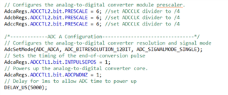
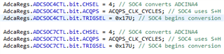
I have configured SOC4 and SOC7 for ADC bank A to sample channel 4 signal which is Phase A grid Voltage.  Below is the code snippet.

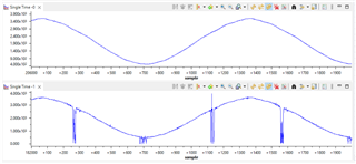
But both result register produce different results and it is dependent on the operating power level of 3-ph, 2-level active front end converter. Top is ResultReg7 and bottom is ResultReg4. Any help as to why this is happening would be really appreciated.

Regards,

Manish Kumar

  • Hello Manish,

    Could you confirm how you've initialized the ADC - in particular, the ADC clock prescale setting?

    Thanks,
    Ibukun

  • Hi Ibukun,

    This is how the ADC has been initialised.

    Thanks,

    Manish Kumar

  • Hello Manish,

    Sorry for the delayed response here.

    My next suggested debug step would be to scope the voltage at the pin to confirm that these fluctuations are internal to the microcontroller and not real.

    Also please describe your input circuit and voltage reference circuit (or provide a schematic of these circuits if possible).

    Thanks,
    Ibukun

  • Hi Ibukun,

    This is the input circuit of AC voltage sensing along with external voltage reference. Please note that, the ADC reference signal is set to external. Also we have probed the voltage at the input of DSP pin, and the signal is clean and can be also noted in SOC7. But on SOC4 the distortion appears which is dependent on the power level the converter is operating on i.e. at power level <4kW SOC4 sensing is clean. The sensed signal on SOC4 starts deteriorating as the power is increased but on SOC7 remains clean. Let me know if any more information is required. (The RC filter near the DSP is designed for cut-off frequency of 4.2kHz)

    Thanks,

    Manish Kumar

  • Hello,

    The image above does not show any details about the signals being connected. What is being connected to VREFHI? Is it a series reference or shunt reference? Is there an op amp? What do those input signals look like? Are they being buffered or conditioned? Is it a resistor divider only? I only see a few wires.

    The correlation to power level (which I assume is some kind of switching noise) probably suggests some power/signal conditioning is insufficient. I would be particularly concerned about the voltage reference circuit in this case.

    Best regards,
    Ibukun