Part Number: TMS320F2800157
Other Parts Discussed in Thread: DRV8353
Tool/software:
Hello team,
As we work on developing the custom board, we tested it with the DRV8353 and the f2800157 launchpad to ensure that the motor operates properly before moving on to the custom board.
In our custom board we are not using DRV8353 gate driver IC instead of this we are using opto-coupler based gate driver IC with same capacity which is already proved with 48v motor running under load condition.
I have the motor electrical parameters like stator resistance, inductance, rated flux, inertia and back emf and replicated the same in universal motor code (UMC).
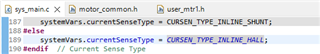
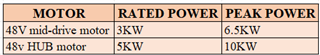
Currently I am running the 48v HALL motor in MOTOR1_HALL with level_4.
I am maintaining the below parameters in UMC.
USER_M1_NOMINAL_DC_BUS_VOLTAGE_V (48.0f)
USER_M1_ADC_FULL_SCALE_VOLTAGE_V (250.658)
USER_M1_VOLTAGE_FILTER_POLE_Hz (375.1100618f)
USER_M1_ADC_FULL_SCALE_CURRENT_A (47.14285714f)
Kp_Id and Kp_Iq= 0.12488495
Ki_Id and Ki_Iq= 0.001312
Kp_spd = 0.224244887
Ki_spd = 0.00224244887
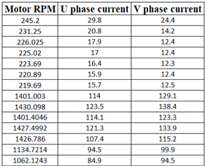
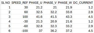
1. We are phasing the issue like motor phase currents are not same and below I have mentioned the all-phase current when I am running in speed_ref = 100f under load condition.
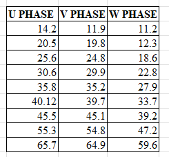
I have tuned the USER_M1_VOLTAGE_FILTER_POLE_Hz, Kp_Id and Kp_Iq values for above issue but still I am not able to resolve.
I have checked this phase current issue in existing system under load condition and here we are getting almost same current consumption in all phases and only 1A difference is there between the phases but in our system, we are getting more than 15 A difference between phases when we increased the load.
Please suggest which parameters we need to calibrate to fix this issue.
Regards,
Kirana H P