TMS320F28379S: Buck converter precision control inquiry

Part Number: TMS320F28379S

Tool/software:

Hi.

I am seeking advice on how to address significant errors in Constant Current control.

Current calibration is being tested by obtaining offset and gain values using an external precision instrument.

H/W Configuration

  • Topology: Buck Non-isolation DC-DC
  • DSP: TMS320F28379S
  • ADC: SDFM + AMC1304M05DW
  • PWM: 50kHz
  • Interrupt: Occurs once every 50kHz

EPwm11 Settings

EPwm11Regs.TBPRD = 1999;
EPwm11Regs.CMPC = 39;
EPwm11Regs.CMPA.bit.CMPA = 1969;

Problems

  1. When set to 3.000A, the error is significant, resulting in a current of about 2.913A.
  2. The error in the output current value changes in the CC control state depending on the output voltage (duty cycle change), even for the same current (e.g., 3A).

When the position of the Shunt Resistor was moved to the final output, CC control did not work.
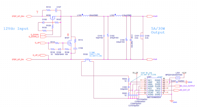
Schematic

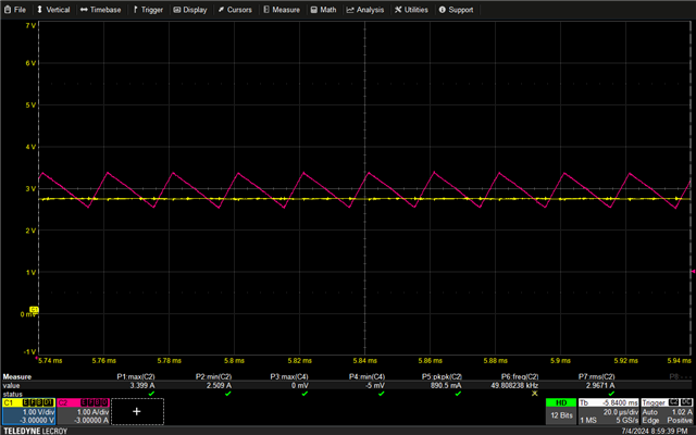
3A Inductor Current Chart

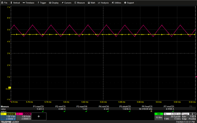
5A Inductor Current Chart

Could you advise on any methods to achieve precise CC control? Have a happy day.

  • Hi

    The expert of topic is currently on vacation. Please expect a response after July 9.

    Thank you

    Amir Hussain

  • Thank you for your message.
    I will wait while doing other work.

  • Hi Bae, 

    Did you refer to any of our reference designs when implementing the CC buck design or have reference source for the software you are using to control the converter?

    Regards,

    Peter

  • Hi Peter Luong1,
    I did not refer to any software.
    The CV PI control is working well.
    The CC PI control is also working well.
    However, due to the voltage consumption of the load (depending on the duty cycle), the error in the controlled current is significant, so I am seeking advice.
    Let me explain the SDFM settings.
    We use ECap1 to generate a 20MHz clock and supply it to the AMC1304.
    Both SDFM1 and SDFM2 are in use, and the shunt resistor is connected to module 2 of SDFM1.
    Below is the setting code.

    void sdfm_pwm11_init(void)
    {
        EALLOW;
        SyncSocRegs.SYNCSELECT.bit.EPWM10SYNCIN = 0;
    
        EPwm11Regs.TBCTL.bit.PRDLD = 0;
        EPwm11Regs.TBCTL2.bit.PRDLDSYNC = 1;
        EPwm11Regs.TBPRD = ((Uint16)(DCDC_PWM_PERIOD) -1);	//EPwm11Regs.TBPRD = 2000
        EPwm11Regs.TBCTR = CLR;
    
        EPwm11Regs.TBCTL.bit.CTRMODE = COUNTER_UP;
        EPwm11Regs.TBCTL.bit.CLKDIV = 0;
        EPwm11Regs.TBCTL.bit.HSPCLKDIV = 0;
    
        EPwm11Regs.CMPA.bit.CMPA = 0;
        EPwm11Regs.CMPCTL.bit.LOADASYNC = 1;
        EPwm11Regs.CMPCTL.bit.LOADAMODE = 0;
        EPwm11Regs.CMPCTL.bit.SHDWAMODE = 0;
    
        EPwm11Regs.AQCTLA.bit.ZRO = TBCTR_CMP_OUTPUT_HIGH;
        EPwm11Regs.AQCTLA.bit.CAU = TBCTR_CMP_OUTPUT_LOW;
    
        EPwm11Regs.TBPHS.bit.TBPHS = 2;
        EPwm11Regs.TBCTL.bit.SYNCOSEL = 0;
        EPwm11Regs.TBCTL.bit.PHSEN = 1;
    
        EPwm11Regs.CMPC = (EPwm11Regs.TBPRD >> 1) - (DCDC_SDFM_PWM_OSR >> 1);                   //EPwm11Regs.TBPRD = 2000, DCDC_SDFM_PWM_OSR = 1920
        EPwm11Regs.CMPD = EPwm11Regs.CMPC;
        EPwm11Regs.CMPA.bit.CMPA = (EPwm11Regs.TBPRD >> 1) + ((DCDC_SDFM_PWM_OSR >> 1) + 10);
    
        EPwm11Regs.ETSEL.bit.INTSELCMP = 0;
        EPwm11Regs.ETSEL.bit.INTSEL = 4;
        EPwm11Regs.ETPS.bit.INTPSSEL = 1;
        EPwm11Regs.ETINTPS.bit.INTPRD2 = 1;
        EPwm11Regs.ETSEL.bit.INTEN = 1;
        EDIS;
    }
    
    
    void sdfm_module1_init(void)
    {
        EALLOW;
        Sdfm1Regs.SDCTLPARM1.bit.MOD = 0;
        Sdfm1Regs.SDCTLPARM2.bit.MOD = 0;
        Sdfm1Regs.SDCTLPARM3.bit.MOD = 0;
        Sdfm1Regs.SDCTLPARM4.bit.MOD = 0;
    
        Sdfm1Regs.SDDFPARM1.bit.FEN = 1;
        Sdfm1Regs.SDDFPARM2.bit.FEN = 1;
        Sdfm1Regs.SDDFPARM3.bit.FEN = 1;
        Sdfm1Regs.SDDFPARM4.bit.FEN = 1;
    
        Sdfm1Regs.SDDFPARM1.bit.SST = 3;
        Sdfm1Regs.SDDFPARM2.bit.SST = 3;
        Sdfm1Regs.SDDFPARM3.bit.SST = 3;
        Sdfm1Regs.SDDFPARM4.bit.SST = 3;
    
        Sdfm1Regs.SDIPARM1.bit.DR = 1;
        Sdfm1Regs.SDIPARM2.bit.DR = 1;
        Sdfm1Regs.SDIPARM3.bit.DR = 1;
        Sdfm1Regs.SDIPARM4.bit.DR = 1;
    
        Sdfm1Regs.SDDFPARM1.bit.DOSR = DCDC_SDFM_OSR - 1;	//DCDC_SDFM_OSR = 128
        Sdfm1Regs.SDDFPARM2.bit.DOSR = DCDC_SDFM_OSR - 1;
        Sdfm1Regs.SDDFPARM3.bit.DOSR = DCDC_SDFM_OSR - 1;
        Sdfm1Regs.SDDFPARM4.bit.DOSR = DCDC_SDFM_OSR - 1;
    
        Sdfm1Regs.SDCPARM1.bit.CS1_CS0 = 3;
        Sdfm1Regs.SDCPARM2.bit.CS1_CS0 = 3;
        Sdfm1Regs.SDCPARM3.bit.CS1_CS0 = 3;
        Sdfm1Regs.SDCPARM4.bit.CS1_CS0 = 3;
    
        Sdfm1Regs.SDCPARM1.bit.COSR = DCDC_SDFM_OVER_SAMPLING -1;	//DCDC_SDFM_OVER_SAMPLING = 32
        Sdfm1Regs.SDCPARM2.bit.COSR = DCDC_SDFM_OVER_SAMPLING -1;
        Sdfm1Regs.SDCPARM3.bit.COSR = DCDC_SDFM_OVER_SAMPLING -1;
        Sdfm1Regs.SDCPARM4.bit.COSR = DCDC_SDFM_OVER_SAMPLING -1;
    
        //-- Protection Level Config --//
        Sdfm1Regs.SDCMPH1.bit.HLT = 0x7FFF;
        Sdfm1Regs.SDCMPL1.bit.LLT = 0x0000;
        Sdfm1Regs.SDCMPH2.bit.HLT = 0x7FFF;
        Sdfm1Regs.SDCMPL2.bit.LLT = 0x0000;
        Sdfm1Regs.SDCMPH3.bit.HLT = 0x7FFF;
        Sdfm1Regs.SDCMPL3.bit.LLT = 0x0000;
        Sdfm1Regs.SDCMPH4.bit.HLT = 0x7FFF;
        Sdfm1Regs.SDCMPL4.bit.LLT = 0x0000;
    
        Sdfm1Regs.SDCMPH2.bit.HLT = DCDC_SDFM_SHUNT_HLT;
        Sdfm1Regs.SDCMPL2.bit.LLT = DCDC_SDFM_SHUNT_LLT;
        Sdfm1Regs.SDCMPH3.bit.HLT = DCDC_SDFM_SHUNTF_HLT;
        Sdfm1Regs.SDCMPL3.bit.LLT = DCDC_SDFM_SHUNTF_LLT;
    
        Sdfm1Regs.SDDFPARM1.bit.FILRESEN = 1;
        Sdfm1Regs.SDDFPARM2.bit.FILRESEN = 1;
        Sdfm1Regs.SDDFPARM3.bit.FILRESEN = 1;
        Sdfm1Regs.SDDFPARM4.bit.FILRESEN = 1;
    
        Sdfm1Regs.SDCPARM1.bit.IEH = 1;
        Sdfm1Regs.SDCPARM2.bit.IEH = 1;
        Sdfm1Regs.SDCPARM3.bit.IEH = 1;
        Sdfm1Regs.SDCPARM4.bit.IEH = 1;
    
        Sdfm1Regs.SDCPARM1.bit.IEL = 1;
        Sdfm1Regs.SDCPARM2.bit.IEL = 1;
        Sdfm1Regs.SDCPARM3.bit.IEL = 1;
        Sdfm1Regs.SDCPARM4.bit.IEL = 1;
    
        Sdfm1Regs.SDMFILEN.bit.MFE = 1;
        Sdfm1Regs.SDCTL.bit.MIE = 1;   
        Sdfm1Regs.SDIFLGCLR.all = 0x8000FFFF;   
        EDIS;
    }
    
    
    static inline void sdfm_data_read(void)
    {
    	//#define DCDC_SDFM_OSR  128
    	//#define DCDC_SDFM_SCALE_FACTOR      (float32)(1.0 / ((float32)DCDC_SDFM_OSR*(float32)DCDC_SDFM_OSR*(float32)DCDC_SDFM_OSR))   //Sinc3 ^3
    	
        sdfm_meas_shunt = (float32)((int32)Sdfm1Regs.SDDATA2.all * DCDC_SDFM_SCALE_FACTOR);         //Shunt
    }

    The DSP model is TMS320F28379SPZPT with a 100-pin package.
    Buck FET control uses PWM2, and for synchronization with PWM11 and PWM12 of SDFM, we operate PWM1 at 50kHz without an external pin.
    Here is the code for that.

    void pwm_dcdc_init(void)
    {
        EALLOW;
        EPwm1Regs.TBCTL.bit.PRDLD = 0;
        EPwm1Regs.TBPRD = ((Uint16)(DCDC_PWM_PERIOD) -1);
        EPwm1Regs.TBCTR = 0;
        EPwm1Regs.TBCTL.bit.CTRMODE = COUNTER_UP;
        EPwm1Regs.TBCTL.bit.CLKDIV = 0;                  
        EPwm1Regs.TBCTL.bit.HSPCLKDIV = 0;
    
        EPwm2Regs.TBCTL.bit.PRDLD = 0;                   
        EPwm2Regs.TBCTL2.bit.PRDLDSYNC = 1;              
        EPwm2Regs.TBPRD = ((Uint16)(DCDC_PWM_PERIOD) -1);
        EPwm2Regs.TBCTR = 0;
        EPwm2Regs.TBCTL.bit.CTRMODE = COUNTER_UP;
        EPwm2Regs.TBCTL.bit.CLKDIV = 0;                  
        EPwm2Regs.TBCTL.bit.HSPCLKDIV = 0;
    
                                                         
        EPwm1Regs.CMPA.bit.CMPA = 0;                     
        EPwm1Regs.CMPCTL.bit.LOADASYNC = 0;              
        EPwm1Regs.CMPCTL.bit.LOADAMODE = 0;              
        EPwm1Regs.CMPCTL.bit.SHDWAMODE = 0;              
    
        EPwm2Regs.CMPA.bit.CMPA = 1;                    
        EPwm2Regs.CMPCTL.bit.LOADASYNC = 1;             
        EPwm2Regs.CMPCTL.bit.LOADAMODE = 0;
        EPwm2Regs.CMPCTL.bit.SHDWAMODE = 0;
    
        EPwm1Regs.AQCTLA.all = 0;                       
        EPwm2Regs.AQCTLA.all = 0;
    
        EPwm1Regs.AQCTLA.bit.CAU = TBCTR_CMP_OUTPUT_LOW;       //if TBCTR=CMPA on Up-Count ---> Output A Low
        EPwm1Regs.AQCTLA.bit.ZRO = TBCTR_CMP_OUTPUT_HIGH;      //if TBCTR=0               ---> Output A High
    
        EPwm2Regs.AQCTLA.bit.ZRO = TBCTR_CMP_OUTPUT_HIGH;
        EPwm2Regs.AQCTLA.bit.CAU = TBCTR_CMP_OUTPUT_LOW;
    
        EPwm2Regs.AQCTLB.bit.ZRO = TBCTR_CMP_OUTPUT_LOW;
        EPwm2Regs.AQCTLB.bit.CAU = TBCTR_CMP_OUTPUT_HIGH;
        EPwm2Regs.AQCTLB.bit.CBU = TBCTR_CMP_OUTPUT_LOW;
    
        EPwm2Regs.DBCTL.bit.HALFCYCLE = 0;         
        EPwm2Regs.DBRED.bit.DBRED = DCDC_PWM_DB;   
        EPwm2Regs.DBFED.bit.DBFED = DCDC_PWM_DB;
    
        EPwm2Regs.DBCTL.bit.IN_MODE = 1;           
        EPwm2Regs.DBCTL.bit.DEDB_MODE = 3;         
        EPwm2Regs.DBCTL.bit.POLSEL = 0;          
        EPwm2Regs.DBCTL.bit.OUT_MODE = 1;        
        EPwm2Regs.DBCTL.bit.OUTSWAP = DBCTL_OUT_SWAP_NONE; 
    
        EPwm1Regs.TBCTL.bit.PHSEN = 0; 
        EPwm1Regs.TBCTL.bit.SYNCOSEL = 1;
    
        EPwm2Regs.TBCTL.bit.PHSEN = 1;
        EPwm2Regs.TBCTL.bit.SYNCOSEL = 0;
    }
    

  • Hi Bae, 

    Thank you for patience given delay in response due to natural disaster.

    Can you help clarify what you mean when you say that there is a large error? I don't see your control code provided which can help. 

    Are you using the average or peak current sensing? Also given the use of delta sigma modulator vs SAR ADC, it seems there is loss of linearity. Could this be coming from the filter?

    Regards,

    Peter

  • Hi Peter,

    We measure current using a Delta-Sigma ADC and do not use an SAR ADC. The interrupt occurs at a PWM frequency of 50kHz, and we have configured the SDFM as follows:
    ```
    sdfm_meas_shunt = (float32)((int32)Sdfm1Regs.SDDATA2.all * DCDC_SDFM_SCALE_FACTOR)
    ```

    Here, the value of DCDC_SDFM_SCALE_FACTOR is calculated using a Sinc3 filter, and the OSR value is 128, with the computed value being 1/128^3.

    We do not use any additional filters, and the ADC value read every 50kHz is input into the PI controller:
    ```
    dcdc_gi_out = DCL_runPI_C1(&dcdc_gi, limit_curr, sdfm_meas_shunt)
    ```

    To convert the value to the actual current, we use offset and gain values:
    ```
    meas_shunt = -sdfm_meas_shunt * CAL_ADC_AS_SR_SLOPE + CAL_ADC_AS_SR_OFFSET
    ```

    We have not used an IIR filter or similar filter but instead used a linear equation to represent the actual value. The current controlled by the PI controller outputs smoothly without oscillation (as shown in the image). However, the sdfm_meas_shunt value (ranging between 0 and 1) and the converted meas_shunt value do not match the actual flowing current.

    This discrepancy occurs because the current value varies with the duty cycle, even when the same amount of current is consumed.

    If you check the CMPC value of SDFM EPwm11 attached to the previous comment, it is 1,920. The current shape in the inductor changes depending on the duty cycle, even if the same current flows, which I believe causes the error.

    Regards,

    Bae