TMS320F28379D:How to use DAC converter with 0 - 3.3V

Part Number: TMS320F28379D
Other Parts Discussed in Thread: C2000WARE

Tool/software:

Hello, good afternoon everyone.

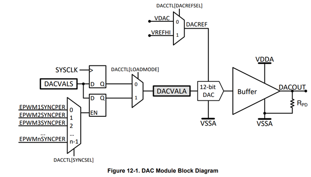
I'm a beginner and I'm programming with Code Composer. I would like to know how to use the digital-to-analog converter with a 0 to 3.3V output. I can only get it to work from 0 to 3V.

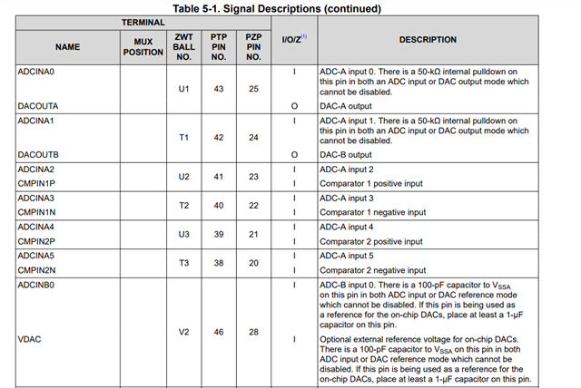
Do I need to indicate in the register that I'm going to use an external reference and then put 3.3V on a specific pin? If so, which pin is this?

  • Hello,

    Thanks for your patience.

    As indictaed  section Buffered DAC Electrical Characteristics in datasheet, the linear region of DAC is 0.3V~(VDDA-0.3)V.

    To configure the external voltage reference, you need to set the DACCTL[DACREFSEL]=0. The related pin is VDAC and information is given Table 5.1. 

  • Hello,

    Thanks for the answer, but I still can't figure out which is the reference pin (VDAC) to which I need to apply 3.3V so that my DAC has an output of 0 to 3.3V. Based on the table above, I connected pin 1 (3.3V) to pin 28 and then connected it to pin 46. But in both tests, my DAC output remains at 0 even when using the DacaRegs.DACVALS.all register = 4095. I can only conclude that these are not the reference pins. (Note: I did not use the recommended 1 uF capacitor)

  • Based on the your device package, you should apply 3.3V to either pin 28 or 46 or V2. 

    I suggest you to run the DAC example given in your C2000ware directory, here C2000Ware_x_xx_00_00\driverlib\f2837xs\examples\cpu1\dac

  • I ran the example and even so the output of pin 30 (DACAUTA) remained at 0 (even putting 3.3V on pin 28 or 46). I would like to know if the information you sent me really applies to the f28379D, because the datasheet says that a voltage of 3.3V should be applied to pin ADCINB0, which according to it corresponds to pin 28. However, looking at my datasheet, pin 28 actually corresponds to ADCINB2. I am sending a print so you can see.

    Do I need to configure pins 28/46 as a GPIO input or something? Or do I simply put 3.3V on them like I was doing? I can't understand why it's not working. Even the workshop examples aren't working.

    I would also like to say that I can't find anywhere what pin V2 would be, so I haven't tested it yet.

  • The pin 28 in the image you were sharing is related to J3 header, not F28379 device.

    I noticed that the option to use VDAC as a pint to apply voltage externally isn't available in LAUNCHPAD. So, you need to use the internal voltage reference.

    In your code, you need to change this function 

    DAC_setReferenceVoltage(DACA_BASE, DAC_REF_VDAC) to the following:
    DAC_setReferenceVoltage(DACA_BASE, DAC_REF_ADC_VREFHI);
  • sure, thanks!
    In other words I only get a 0 to 3V output from the DAC of the f28379D device?

  • The linear region of DAC is 0.3V~(VDDA-0.3)V; so, the output of DAC is 0.3V~3V.