Part Number: TMS320F280049C
Tool/software:
Hi,
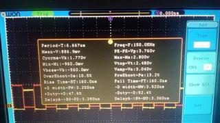
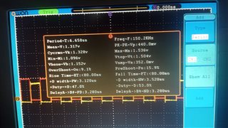
I'm trying to generate 2 inverted PWMs, each pwm has 50% duty cycle and there is a dead band of 200ns between the signals, the Dead band is generated flawlessly
But My problem ,s I can't get precise duty cycle values it varies between 47% - 53% as seen in the oscilloscope pic. below
So how could i achieve precise duty cycle(exactly 50%) while maintaining the dead band (Code is )
#include "f28x_Project.h"
__interrupt void epwm1_ISR(void);
__interrupt void epwm2_ISR(void);
//PWM Period= (2×Desired Frequency) / System Clock
Uint16 pwm_period = 333; // 150 kHz frequency with 100 MHz clock
Uint16 duty_cycle_cmpa = 166; // 50% duty cycle (TBPRD/2)
Uint16 deadband_value = 20; // 200 ns deadband (20 clock cycles)
void main(void)
{
// Initialize system
InitSysCtrl();
// Disable interrupts
DINT;
// Clear interrupts
IER = 0x0000;
IFR = 0x0000;
// Initialize peripherals
InitPieCtrl();
// Initialize PIE vector table
InitPieVectTable();
// Assign our ISR addresses to the elements in vector table
EALLOW;
PieVectTable.EPWM1_INT = &epwm1_ISR;
PieVectTable.EPWM2_INT = &epwm2_ISR;
EDIS;
// Enable ePWM1 and ePWM2 clocks
EALLOW;
CpuSysRegs.PCLKCR2.bit.EPWM1 = 1;
CpuSysRegs.PCLKCR2.bit.EPWM2 = 1;
EDIS;
// Configure ePWM1
EPwm1Regs.TBPRD = pwm_period; // Set 150 kHz period
EPwm1Regs.TBCTL.bit.CTRMODE = 2; // Up-down count mode
EPwm1Regs.TBCTL.bit.HSPCLKDIV = 0; // No high-speed clock divider
EPwm1Regs.TBCTL.bit.CLKDIV = 0; // No clock divider
EPwm1Regs.CMPA.bit.CMPA = pwm_period/2; // 50% duty cycle
// Configure Action Qualifier for ePWM1 A and B
EPwm1Regs.AQCTLA.bit.CAU = AQ_CLEAR; // Clear PWM on CMPA up count
EPwm1Regs.AQCTLA.bit.CAD = AQ_SET; // Set PWM on CMPA down count
EPwm1Regs.AQCTLB.bit.CAU = AQ_CLEAR; // Set PWM on CMPA up count
EPwm1Regs.AQCTLB.bit.CAD = AQ_SET; // Clear PWM on CMPA down count
// Dead band configuration for ePWM1
EPwm1Regs.DBCTL.bit.IN_MODE = 1; // EPWMxA as source for both rising and falling edges
EPwm1Regs.DBCTL.bit.POLSEL = 2; // Active low complementary mode
EPwm1Regs.DBCTL.bit.OUT_MODE = 3; // Deadband fully enabled
EPwm1Regs.DBRED.bit.DBRED = deadband_value; // Rising edge delay
EPwm1Regs.DBFED.bit.DBFED = deadband_value; // Falling edge delay
// Configure ePWM2 similarly
EPwm2Regs.TBPRD = pwm_period;
EPwm2Regs.TBCTL.bit.CTRMODE = 2; // Up-down count mode
EPwm2Regs.TBCTL.bit.HSPCLKDIV = 0;
EPwm2Regs.TBCTL.bit.CLKDIV = 0;
EPwm2Regs.CMPA.bit.CMPA = pwm_period/2; // 50% duty cycle
EPwm2Regs.AQCTLA.bit.CAU = AQ_CLEAR;
EPwm2Regs.AQCTLA.bit.CAD = AQ_SET;
EPwm2Regs.AQCTLB.bit.CAU = AQ_CLEAR;
EPwm2Regs.AQCTLB.bit.CAD = AQ_SET;
// Dead band configuration for ePWM2
EPwm2Regs.DBCTL.bit.IN_MODE = 1;
EPwm2Regs.DBCTL.bit.POLSEL = 2;
EPwm2Regs.DBCTL.bit.OUT_MODE = 3;
EPwm2Regs.DBRED.bit.DBRED = deadband_value;
EPwm2Regs.DBFED.bit.DBFED = deadband_value;
// Enable PIE interrupts for ePWM1 and ePWM2
PieCtrlRegs.PIEIER3.bit.INTx1 = 1;
PieCtrlRegs.PIEIER3.bit.INTx2 = 1;
// Enable group interrupts in IER
IER |= M_INT3;
// Enable global interrupts
EINT;
// Setup GPIO pins for ePWM1 and ePWM2
EALLOW;
GpioCtrlRegs.GPAMUX1.bit.GPIO0 = 1; // ePWM1A
GpioCtrlRegs.GPAMUX1.bit.GPIO1 = 1; // ePWM1B
GpioCtrlRegs.GPAMUX1.bit.GPIO2 = 1; // ePWM2A
GpioCtrlRegs.GPAMUX1.bit.GPIO3 = 1; // ePWM2B
EDIS;
// Infinite loop
for (;;);
}
// ISR for ePWM1
__interrupt void epwm1_ISR(void)
{
// Clear interrupt flag
EPwm1Regs.ETCLR.bit.INT = 1;
// Acknowledge interrupt in PIE
PieCtrlRegs.PIEACK.bit.ACK3 = 1;
}
// ISR for ePWM2
__interrupt void epwm2_ISR(void)
{
// Clear interrupt flag
EPwm2Regs.ETCLR.bit.INT = 1;
// Acknowledge interrupt in PIE
PieCtrlRegs.PIEACK.bit.ACK3 = 1;
}