This thread has been locked.

If you have a related question, please click the "Ask a related question" button in the top right corner. The newly created question will be automatically linked to this question.

TMS320F28P650DK: ADC Configuration Issue with F28P65x (TMS320F28P650DK).

Part Number: TMS320F28P650DK
Other Parts Discussed in Thread: C2000WARE, LAUNCHXL-F28P65X, SYSCONFIG

Tool/software:

Team facing issue with ADC Configuration F28P65x

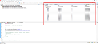
We require assistance with configuring the ADC on the F28P65x module (TMS320F28P650DK9). We are using Code Composer Studio (CCS) IDE and have imported the existing ADC example from the following path:
C:\ti\C2000Ware_5_04_00_00\driverlib\f28p65x\examples\c28x\adc.

We have made the necessary hardware changes to the GPIO configuration and connected the respective GPIO pin. However, we are not obtaining the expected results. Specifically, when we run the code in debug mode, the myADC1Result parameter continuously updates, even when no voltage is applied to the corresponding pin.

We have also tried other ADC examples provided in the library but have not been able to resolve the issue. Our primary goal is to successfully configure and run the ADC on the F28P65x board.

Please find attached:

  1. Screenshots of the current ADC configuration.
  2. Debug mode output results/video for your reference.

Could you please review and let us know if we are missing any steps or making an error in the configuration? Any guidance or additional steps would be greatly appreciated.

Thank you for your support!

Regards,
Arun S


  • Hi Arun,

    Can you let me know the Hardware you are using to test this ?

    Launchxl-f28p65x or TMDSCNCD28P65x or you are using a Custom made hardware for this.

    BR,

    Nilesh

  • Hi Nilesh,

    Thank you for your reply, We are using LAUNCHXL-F28P65X C2000Tm real-time MCU F28P65x LaunchPadTm development kit (TMS320F28P650DK9) hardware, this is not custom hardware.

    Regards,

    Arun S

  • Hi Arun,

    Thanks for answering the question, just wanted to remove any hardware dependency. 

    I had few queries related to configuration:

    • Can you let me know the Voltage you are feeding to the ADC input (A4 ) , so that we know what output is expected by ADC in CCS expersions ?
    • Can you share the "Analog Pin mux"  , 3rd menu in the analog section of Sysconfig tool . 
    • Also if you plan to use 2 or more ADC's would suggest to use "adc_ex2_soc_epwm" example 

    BR,

    Nilesh

  • Hi Nilesh,

    Thank you for reply, based on your question below is my response:

    • We are trying with multiple value on A4 (5v, 3.3v, GND) but output is same as enclosed in my very first query.
    • I have enclosed it below.
    • Sure will try with "adc_ex2_soc_epwm" example.

    Also can you tell, Should we use the same configuration given in example or we can try with "Use case Custom" as per hardware pin configuration and select the pin accordingly?

    Edited: We tried with the  "adc_ex2_soc_epwm" example but result is same(Value 195 is not changing as per input vlg, 3.3v, 5v, GND) screenshot enclosed below

    Regards,
    Arun S

    "Analog Pin mux" 


    "adc_ex2_soc_epwm" example result.


  • Hi Arun,

    Thanks for answering the questions: 

    • We are trying with multiple value on A4 (5v, 3.3v, GND) but output is same as enclosed in my very first query.
    5V is not a recommended input voltage for device, voltages <=3.3V are only recomended. 
  • By default the reference selected in the example is for Internal 1.65 (Full scale Voltage range =3.3) 
    • Can confirm this by looking at the 4th Menu "ASYSCTL"
  •  For pin configuration i would recomend to use the default configuration as the tool will take care for selecting the right settings for the input pin
    •  If you go with deafult option all pins will be selected (Image below) 
    •   
    • The actual channel selection can be taken care by SOCx channel selection under  ADC menu (eg: for A4 --> ADCIN4 )

Also make sure to choose the correct Package of the device, as you are using LAUNCH PAD you can select the 169NMR.

Refresh the pin mux config once to "All" again if it show an error after changing package. 

Try the above changes and check if you are getting the expected ADC code.

For providing ADC input :

  • Can use external supply to provide input (0- 3.3 in this case)
  • For initial checks you can use J15 Pin 1 to provide input to ADC, you would get 1.65V Reference voltage on this pin (Only when ADC is eanbled) 
  • If you want variable input on board can use internal DAC(Configuration required) as well to loop back the voltage to ADC 

BR,

Nilesh