This thread has been locked.
If you have a related question, please click the "Ask a related question" button in the top right corner. The newly created question will be automatically linked to this question.
HI
I am trying to communicate to a PC using SCI of F28335.I am currently using max232 IC as the RS-232 cable was not available for now.
We ran the echoback program given in control suite for F28069 with the same IC circuit by changing the SCIHBAUD to 0x01(earlier 0x0000) and SCILbaud to 0x03 (earlier 0x0103).It was succesfully done.we could see on the hyperterminal the sent and the recieve character.
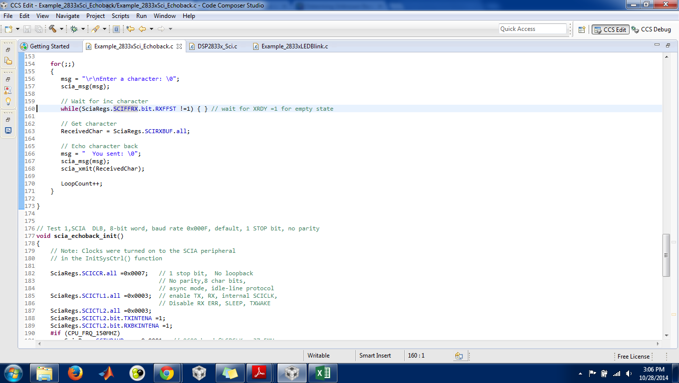
But running echoback program for F28335 is'nt echoing back the value we are enetring. We changed the SCIHBAUD to SciaRegs.SCIHBAUD =0x01 (earlier 0x0001) and SCILBAUD to 0xE7(earlier 0x00E7).I am looking for baud rate 9600.
I can enter the character but DSP does not echoback the same.
What am I missing?
thanks
Sneha
Hi Sneha,
Did you check whether the baud rate set is 9600 on DSO? Transmit some data in while loop and check the baud rate of the data transmitted.
Regards,
Gautam
Hi Gautam
Thanks for your prompt reply.
But I am still confused.Checking baud rate on DSO?I am checking the output between Tx pin and ground.But I get nothing on DSO.And while running the program loopcount doesn't increments. it stops at line 160 as shwn in the screenshot.
Kindly guide me.
Thanks
Sneha
Exactly, because its waiting at the receive interrupt. You need to remove all the receive routines and just have a sci transmit routine that polls data in a while loop, only then you'll be able to observe the data on dso.
Regards,
Gautam
HI Gautam
Checked the same.I am attaching the code which i changed for the same.The baud rate is (1/104) micro-secs = 9615.
Please suggest what changes have to be included in order to have this program running.
// TI File $Revision: /main/2 $ // Checkin $Date: July 30, 2009 18:45:31 $ //########################################################################### // // FILE: Example_2833xSci_Echoback.c // // TITLE: DSP2833x Device SCI Echoback. // // ASSUMPTIONS: // // This program requires the DSP2833x header files. // As supplied, this project is configured for "boot to SARAM" operation. // // Connect the SCI-A port to a PC via a transciever and cable. // The PC application 'hypterterminal' can be used to view the data // from the SCI and to send information to the SCI. Characters recieved // by the SCI port are sent back to the host. // // As supplied, this project is configured for "boot to SARAM" // operation. The 2833x Boot Mode table is shown below. // For information on configuring the boot mode of an eZdsp, // please refer to the documentation included with the eZdsp, // // $Boot_Table: // // GPIO87 GPIO86 GPIO85 GPIO84 // XA15 XA14 XA13 XA12 // PU PU PU PU // ========================================== // 1 1 1 1 Jump to Flash // 1 1 1 0 SCI-A boot // 1 1 0 1 SPI-A boot // 1 1 0 0 I2C-A boot // 1 0 1 1 eCAN-A boot // 1 0 1 0 McBSP-A boot // 1 0 0 1 Jump to XINTF x16 // 1 0 0 0 Jump to XINTF x32 // 0 1 1 1 Jump to OTP // 0 1 1 0 Parallel GPIO I/O boot // 0 1 0 1 Parallel XINTF boot // 0 1 0 0 Jump to SARAM <- "boot to SARAM" // 0 0 1 1 Branch to check boot mode // 0 0 1 0 Boot to flash, bypass ADC cal // 0 0 0 1 Boot to SARAM, bypass ADC cal // 0 0 0 0 Boot to SCI-A, bypass ADC cal // Boot_Table_End$ // // DESCRIPTION: // // // This test recieves and echo-backs data through the SCI-A port. // // 1) Configure hyperterminal: // Use the included hyperterminal configuration file SCI_96.ht. // To load this configuration in hyperterminal: file->open // and then select the SCI_96.ht file. // 2) Check the COM port. // The configuration file is currently setup for COM1. // If this is not correct, disconnect Call->Disconnect // Open the File-Properties dialog and select the correct COM port. // 3) Connect hyperterminal Call->Call // and then start the 2833x SCI echoback program execution. // 4) The program will print out a greeting and then ask you to // enter a character which it will echo back to hyperterminal. // // As is, the program configures SCI-A for 9600 baud with // SYSCLKOUT = 150MHz and LSPCLK = 37.5 MHz // SYSCLKOUT = 100MHz and LSPCLK = 25.0 Mhz // // // Watch Variables: // LoopCount for the number of characters sent // ErrorCount // // //########################################################################### // $TI Release: 2833x/2823x Header Files V1.32 $ // $Release Date: June 28, 2010 $ //########################################################################### #include "DSP28x_Project.h" // Device Headerfile and Examples Include File // Prototype statements for functions found within this file. void scia_echoback_init(void); void scia_fifo_init(void); void scia_xmit(int a); void scia_msg(char *msg); // Global counts used in this example Uint16 LoopCount; Uint16 ErrorCount; void main(void) { Uint16 ReceivedChar; char *msg; // Step 1. Initialize System Control: // PLL, WatchDog, enable Peripheral Clocks // This example function is found in the DSP2833x_SysCtrl.c file. InitSysCtrl(); // Step 2. Initalize GPIO: // This example function is found in the DSP2833x_Gpio.c file and // illustrates how to set the GPIO to it's default state. // InitGpio(); Skipped for this example // For this example, only init the pins for the SCI-A port. // This function is found in the DSP2833x_Sci.c file. InitSciaGpio(); // Step 3. Clear all interrupts and initialize PIE vector table: // Disable CPU interrupts DINT; // Initialize PIE control registers to their default state. // The default state is all PIE interrupts disabled and flags // are cleared. // This function is found in the DSP2833x_PieCtrl.c file. InitPieCtrl(); // Disable CPU interrupts and clear all CPU interrupt flags: IER = 0x0000; IFR = 0x0000; // Initialize the PIE vector table with pointers to the shell Interrupt // Service Routines (ISR). // This will populate the entire table, even if the interrupt // is not used in this example. This is useful for debug purposes. // The shell ISR routines are found in DSP2833x_DefaultIsr.c. // This function is found in DSP2833x_PieVect.c. InitPieVectTable(); // Step 4. Initialize all the Device Peripherals: // This function is found in DSP2833x_InitPeripherals.c // InitPeripherals(); // Not required for this example // Step 5. User specific code: LoopCount = 0; ErrorCount = 0; scia_fifo_init(); // Initialize the SCI FIFO scia_echoback_init(); // Initalize SCI for echoback msg = "\r\n\n\nHello World!\0"; scia_msg(msg); msg = "\r\nYou will enter a character, and the DSP will echo it back! \n\0"; scia_msg(msg); for(;;) { msg = "\r\nEnter a character: \0"; scia_msg(msg); // Wait for inc character // while(SciaRegs.SCIFFRX.bit.RXFFST !=1) { } // wait for XRDY =1 for empty state // Get character // ReceivedChar = SciaRegs.SCIRXBUF.all; // Echo character back // msg = " You sent: \0"; // scia_msg(msg); // scia_xmit(ReceivedChar); LoopCount++; } } // Test 1,SCIA DLB, 8-bit word, baud rate 0x000F, default, 1 STOP bit, no parity void scia_echoback_init() { // Note: Clocks were turned on to the SCIA peripheral // in the InitSysCtrl() function SciaRegs.SCICCR.all =0x0007; // 1 stop bit, No loopback // No parity,8 char bits, // async mode, idle-line protocol SciaRegs.SCICTL1.all =0x0002; // enable TX, disable RX, internal SCICLK,(earlier 0003correct one) // Disable RX ERR, SLEEP, TXWAKE SciaRegs.SCICTL2.all =0x0001; // initially the correct oneis 0003 SciaRegs.SCICTL2.bit.TXINTENA =1; //SciaRegs.SCICTL2.bit.RXBKINTENA =1; #if (CPU_FRQ_150MHZ) SciaRegs.SCIHBAUD =0x0001; // 9600 baud @LSPCLK = 37.5MHz. SciaRegs.SCILBAUD =0x00E7; #endif #if (CPU_FRQ_100MHZ) SciaRegs.SCIHBAUD =0x0001; // 9600 baud @LSPCLK = 20MHz. SciaRegs.SCILBAUD =0x0044; #endif SciaRegs.SCICTL1.all =0x0022; // Relinquish SCI from Reset(initially 0023) } // Transmit a character from the SCI void scia_xmit(int a) { while (SciaRegs.SCIFFTX.bit.TXFFST != 0) {} SciaRegs.SCITXBUF=a; } void scia_msg(char * msg) { int i; i = 0; while(msg[i] != '\0') { scia_xmit(msg[i]); i++; } } // Initalize the SCI FIFO void scia_fifo_init() { SciaRegs.SCIFFTX.all=0xE040; SciaRegs.SCIFFRX.all=0x204f; // SciaRegs.SCIFFCT.all=0x0; } //=========================================================================== // No more. //===========================================================================
Thanks
Sneha
Sneha Thakur said:Checked the same.I am attaching the code which i changed for the same.The baud rate is (1/104) micro-secs = 9615.
Please suggest what changes have to be included in order to have this program running.
Before doing this, I would like you to check the same with the other controller. Same transmission in a while loop... preferably same data and then compare the waveforms. The baudrate should match for the communication to happen.
Regards,
Gautam
Oki gautam I will check it for F28069 and reply in a while.
But What if want to implement the echoback program for one controller.Its not running with F28335.
on the hyperterminal it asks to input the character, but after that nothing happens.
thanks
Sneha
Hi Gautam
I checked the waveforms for F28069 control stick.It's programmed for 9600 baud rate with LSPCLK = 20 MHz.
The baud rate and waveforms are similar for both f28335 and f28069
Please find attached the waveform and the program.
// TI File $Revision: /main/2 $ // Checkin $Date: January 4, 2011 10:03:22 $ //########################################################################### // // FILE: Example_2806xSci_Echoback.c // // TITLE: F2806x Device SCI Echoback. // // ASSUMPTIONS: // // This program requires the F2806x header files. // As supplied, this project is configured for "boot to SARAM" operation. // // Connect the SCI-A port to a PC via a transciever and cable. // The PC application 'hypterterminal' can be used to view the data // from the SCI and to send information to the SCI. Characters recieved // by the SCI port are sent back to the host. // // As supplied, this project is configured for "boot to SARAM" // operation. The F2806x Boot Mode table is shown below. // $Boot_Table: // // While an emulator is connected to your device, the TRSTn pin = 1, // which sets the device into EMU_BOOT boot mode. In this mode, the // peripheral boot modes are as follows: // // Boot Mode: EMU_KEY EMU_BMODE // (0xD00) (0xD01) // --------------------------------------- // Wait !=0x55AA X // I/O 0x55AA 0x0000 // SCI 0x55AA 0x0001 // Wait 0x55AA 0x0002 // Get_Mode 0x55AA 0x0003 // SPI 0x55AA 0x0004 // I2C 0x55AA 0x0005 // OTP 0x55AA 0x0006 // ECANA 0x55AA 0x0007 // SARAM 0x55AA 0x000A <-- "Boot to SARAM" // Flash 0x55AA 0x000B // Wait 0x55AA Other // // Write EMU_KEY to 0xD00 and EMU_BMODE to 0xD01 via the debugger // according to the Boot Mode Table above. Build/Load project, // Reset the device, and Run example // // $End_Boot_Table // // // Description: // // // This test recieves and echo-backs data through the SCI-A port. // // 1) Configure hyperterminal: // Use the included hyperterminal configuration file SCI_96.ht. // To load this configuration in hyperterminal: file->open // and then select the SCI_96.ht file. // 2) Check the COM port. // The configuration file is currently setup for COM1. // If this is not correct, disconnect Call->Disconnect // Open the File-Properties dialog and select the correct COM port. // 3) Connect hyperterminal Call->Call // and then start the F2806x SCI echoback program execution. // 4) The program will print out a greeting and then ask you to // enter a character which it will echo back to hyperterminal. // // // Watch Variables: // LoopCount for the number of characters sent // ErrorCount // // //########################################################################### // $TI Release: 2806x C/C++ Header Files and Peripheral Examples V1.00 $ // $Release Date: January 11, 2011 $ //########################################################################### #include "DSP28x_Project.h" // Device Headerfile and Examples Include File // Prototype statements for functions found within this file. void scia_echoback_init(void); void scia_fifo_init(void); void scia_xmit(int a); void scia_msg(char *msg); // Global counts used in this example Uint16 LoopCount; Uint16 ErrorCount; void main(void) { Uint16 ReceivedChar; char *msg; // Step 1. Initialize System Control: // PLL, WatchDog, enable Peripheral Clocks // This example function is found in the F2806x_SysCtrl.c file. InitSysCtrl(); // Step 2. Initalize GPIO: // This example function is found in the F2806x_Gpio.c file and // illustrates how to set the GPIO to it's default state. // InitGpio(); Skipped for this example // For this example, only init the pins for the SCI-A port. // This function is found in the F2806x_Sci.c file. InitSciaGpio(); // Step 3. Clear all interrupts and initialize PIE vector table: // Disable CPU interrupts DINT; // Initialize PIE control registers to their default state. // The default state is all PIE interrupts disabled and flags // are cleared. // This function is found in the F2806x_PieCtrl.c file. InitPieCtrl(); // Disable CPU interrupts and clear all CPU interrupt flags: IER = 0x0000; IFR = 0x0000; // Initialize the PIE vector table with pointers to the shell Interrupt // Service Routines (ISR). // This will populate the entire table, even if the interrupt // is not used in this example. This is useful for debug purposes. // The shell ISR routines are found in F2806x_DefaultIsr.c. // This function is found in F2806x_PieVect.c. InitPieVectTable(); // Step 4. Initialize all the Device Peripherals: // This function is found in F2806x_InitPeripherals.c // InitPeripherals(); // Not required for this example // Step 5. User specific code: LoopCount = 0; ErrorCount = 0; scia_fifo_init(); // Initialize the SCI FIFO scia_echoback_init(); // Initalize SCI for echoback msg = "\r\n\n\nHello World!\0"; scia_msg(msg); msg = "\r\nYou will enter a character, and the DSP will echo it back! \n\0"; scia_msg(msg); for(;;) { msg = "\r\nEnter a character: \0"; scia_msg(msg); // Wait for inc character // while(SciaRegs.SCIFFRX.bit.RXFFST !=1) { } // wait for XRDY =1 for empty state // Get character // ReceivedChar = SciaRegs.SCIRXBUF.all; // Echo character back // msg = " You sent: \0"; // scia_msg(msg); // scia_xmit(ReceivedChar); LoopCount++; } } // Test 1,SCIA DLB, 8-bit word, baud rate 0x000F, default, 1 STOP bit, no parity void scia_echoback_init() { // Note: Clocks were turned on to the SCIA peripheral // in the InitSysCtrl() function SciaRegs.SCICCR.all =0x0007; // 1 stop bit, No loopback // No parity,8 char bits, // async mode, idle-line protocol SciaRegs.SCICTL1.all =0x0002; // enable TX, RX, internal SCICLK,0003 // Disable RX ERR, SLEEP, TXWAKE SciaRegs.SCICTL2.all =0x0001;//0003 SciaRegs.SCICTL2.bit.TXINTENA =1; //SciaRegs.SCICTL2.bit.RXBKINTENA =1; SciaRegs.SCIHBAUD =0x01; // 9600 baud @LSPCLK = 20MHz (80 MHz SYSCLK). SciaRegs.SCILBAUD =0x03; SciaRegs.SCICTL1.all =0x0022; // Relinquish SCI from Reset0023 } // Transmit a character from the SCI void scia_xmit(int a) { while (SciaRegs.SCIFFTX.bit.TXFFST != 0) {} SciaRegs.SCITXBUF=a; } void scia_msg(char * msg) { int i; i = 0; while(msg[i] != '\0') { scia_xmit(msg[i]); i++; } } // Initalize the SCI FIFO void scia_fifo_init() { SciaRegs.SCIFFTX.all=0xE040; //SciaRegs.SCIFFRX.all=0x2044; SciaRegs.SCIFFCT.all=0x0; } //=========================================================================== // No more. //===========================================================================
Please let me know how to move ahead with communication between these two controllers?
How to change the LSPCLK value?
How to establish echoback program with F28335 as asked in my previous post.
Thanks
Sneha
Sneha Thakur said:Please let me know how to move ahead with communication between these two controllers?
Now that the baud rates are matching... ! We're good to go ahead. You can use the same transmission code on one end and receive interrupt on the other side. Transmission controller will not require any debugging, instead you can debug the receiver and check the SCI global variables for the received data. Don't send data continuously in a while loop... instead send one at a time in short every reset should send one data that you should be able to observe on debug window.
Regards,
Gautam
Hi Gautam
Thanks for the reply.
Will get back to you soon.let me first make an attempt .
Thanks
Sneha
Hi
I am not able to communicate with F28335 using SCI.I am running the SCI_Echoback program from control suite fo r F28335.But its not working.
The same program worked successfully for F28069 control stick.
I am attaching the screenshot of hyperterminal screen and the watch window.the loopcount does not increments and stucks at the line waiting for recieve interrupt.
The baud rate is 9600 set as 0001,00E7 for SCIHBAUD,SCILBAUD for LSPCLK 37.5 MHz.
Kindly help
Thank
Sneha
Hi gautam
I wasn't connecting the ground pin.
With F28069 I just connected Tx and Rx pins to FT232RL IC circuits Rx and Tx pins and it worked successfully.
But It is not working for F28335.I tried by connecteing the ground pins together too,but the same resukt.
Please suggest.
Thanks
Sneha
Hi Gautam
The problem is resolved,without connecting the ground pins.
I changes the GPIO pins.Earlier I was checking on GPIO 28 and 29 SCIA and itdidnot run.
By chnaging it to SCIB i.e. GPIO18 and 19 It worked.
Thanks for all your support.
Kindly help me with communication between two controllers as posted in the other forum.
http://e2e.ti.com/support/microcontrollers/c2000/f/171/p/378316/1332928.aspx#1332928
Thanks
Sneha
That's Great, Sneha! but....
Sneha Thakur said:The problem is resolved,without connecting the ground pins.
Ground pin is a must when you go for custom boards where power supplies might be different. For now as the power supply is same for both you're able to observe the communication.
Goodluck & Regards,
Gautam
Oh thanks Guatam.
I will keep that in mind.And does it concludes that GPIO28 Rx pin is not working. As I couldn't establish communication with that?
Thanks
Sneha
Sneha Thakur said:And does it concludes that GPIO28 Rx pin is not working. As I couldn't establish communication with that?
Actually it should work, I guess some miss-configuration else it should've worked!
Regards,
Gautam