

Other Parts Discussed in Thread: TMS320F28069, AM3359, ADC141S626
Hi,
I am using the TMS320F28069 microcontroller as a mid point of an ADC data collection process. One of the SPI drivers (SPIA) is used in master mode to collect data from an external ADC (ADC141S626, not the one built in), then data are imported into an array, once the array is filled, SPIB in slave mode transmit data to Beaglebone Black(AM3359) for further use and storage. The code for F28069 is pasted belown:
#include "DSP28x_Project.h"     // Device Headerfile and Examples Include File
#include <stdio.h>      /* printf */
#include <math.h>

// Configure if ePWM timer interrupt is enabled at the PIE level:
// 1 = enabled,  0 = disabled
#define PWM1_INT_ENABLE  1

// Configure the period for the timer
#define PWM1_TIMER_TBPRD   0x5FFF

// Prototype statements for functions found within this file.
interrupt void epwm1_timer_isr(void);

// Prototype statements for functions found within this file.
void spi_fifo_init(void);
void spi_init(void);
void InitEPwmTimer(void);

//Global Variables
Uint16 rdata1[500] = {0};  // received data buffer1
Uint16 rdata2[500] = {0};  // received data buffer2
Uint16 dummy;
int bufferflag = 1;	//which buffer has the most current data
int readytxflag = 0;	//if one buffer is filled
int i = 0;	//output counter
int n = 0;	//input counter

void main(void)
{

// PLL, WatchDog, enable Peripheral Clocks
// This example function is found in the F2806x_SysCtrl.c file.
   InitSysCtrl();

// This example function is found in the F2806x_Gpio.c file and
// illustrates how to set the GPIO to it's default state.
// InitGpio();  // Skipped for this example
// Setup only the GP I/O only for SPI-A functionality
// This function is found in F2806x_Spi.c
   InitSpiaGpio();
   InitSpibGpio();

// Disable CPU interrupts
   DINT;

// Initialize PIE control registers to their default state.
// The default state is all PIE interrupts disabled and flags
// are cleared.
// This function is found in the F2806x_PieCtrl.c file.
   InitPieCtrl();

// Disable CPU interrupts and clear all CPU interrupt flags:
   IER = 0x0000;
   IFR = 0x0000;

// Initialize the PIE vector table with pointers to the shell Interrupt
// Service Routines (ISR).
// This will populate the entire table, even if the interrupt
// is not used in this example.  This is useful for debug purposes.
// The shell ISR routines are found in F2806x_DefaultIsr.c.
// This function is found in F2806x_PieVect.c.
   InitPieVectTable();

// Interrupt that is used in this example is re-mapped to
// ISR function found within this file.
	EALLOW;  // This is needed to write to EALLOW protected registers
	PieVectTable.EPWM1_INT = &epwm1_timer_isr;
	EDIS;    // This is needed to disable write to EALLOW protected registers

// This function is found in F2806x_InitPeripherals.c
// InitPeripherals();  // Not required for this example
	InitEPwmTimer();    // For this example, only initialize the ePWM Timer
	spi_fifo_init();	  // Initialize the Spi FIFO
	spi_init();		  // init SPI

// Enable CPU INT3 which is connected to EPWM1-6 INT:
	IER |= M_INT3;

// Enable EPWM INTn in the PIE: Group 3 interrupt 1-6
	PieCtrlRegs.PIEIER3.bit.INTx1 = PWM1_INT_ENABLE;

// Initially disable time-critical interrupts
	SetDBGIER(0x0000);   //PIE groups time-critical designation

// Enable global Interrupts and higher priority real-time debug events:
	EINT;   // Enable Global interrupt INTM
	ERTM;   // Enable Global realtime interrupt DBGM

//**************** Send data to BBB*****************
	for(;;)
	{
	     if (readytxflag == 1)
	     {
		  for(i = 0; i < sizeof(rdata1); i++)
		  {
                     if (bufferflag == 2)
	   		temp=rdata1[i];
		     if (bufferflag == 1)
	   		temp=rdata2[i];
                     SpiaRegs.SPITXBUF=temp;
		     while(SpiaRegs.SPISTS.bit.INT_FLAG != 1) {}
		  }
		  readytxflag = 0;
	     }
	}
}

//*****************Receive data from ADC**************
interrupt void epwm1_timer_isr(void)
{

	// Clear INT flag for this timer
	EPwm1Regs.ETCLR.bit.INT = 1;

	SpibRegs.SPITXBUF = dummy; // Send dummy to start tx
	while(SpibRegs.SPISTS.bit.INT_FLAG !=1) {} // Wait until data received
	if (bufferflag == 1)
		rdata1[n] = SpibRegs.SPIRXBUF; // Master reads data
	if (bufferflag == 2)
		rdata2[n] = SpibRegs.SPIRXBUF; // Master reads data

	n++;

	//if buffer full, change buffer
	if (n == sizeof(rdata1))
	{
		if (bufferflag ==1)
			bufferflag = 2;
		else
			bufferflag = 1;
		n = 0;
		readytxflag = 1;
	}

	// Acknowledge this interrupt to receive more interrupts from group 3
	PieCtrlRegs.PIEACK.all = PIEACK_GROUP3;

}
//

// Step 7. Insert all local Interrupt Service Routines (ISRs) and functions here:
void spi_init()
{

    SpiaRegs.SPICCR.all =0x000F;	             // Reset on, rising edge, 16-bit char bits
    SpiaRegs.SPICTL.all =0x0002;    		     // Enable slave mode, normal phase,
    SpiaRegs.SPIBRR =0x007F;			     // enable talk, and SPI int disabled.
    SpiaRegs.SPICCR.all =0x008F;		     // Relinquish SPI from Reset
    SpiaRegs.SPIPRI.bit.FREE = 1;                    // Set so breakpoints don't disturb xmission
    SpiaRegs.SPIPRI.bit.TRIWIRE = 0;

    SpibRegs.SPICCR.all =0x000F;	             // Reset on, rising edge, 16-bit char bits
    SpibRegs.SPICTL.all =0x0006;    		     // Enable master mode, normal phase,
    SpibRegs.SPIBRR =0x007F;			     // enable talk, and SPI int disabled.
    SpibRegs.SPICCR.all =0x008F;		     // Relinquish SPI from Reset
    SpibRegs.SPIPRI.bit.FREE = 1;                    // Set so breakpoints don't disturb xmission

}

void spi_fifo_init()
{

// Initialize SPI FIFO registers

    SpiaRegs.SPIFFTX.all=0xE020;
    SpiaRegs.SPIFFCT.all=0x0;

    SpibRegs.SPIFFRX.all=0x6060;
    SpibRegs.SPIFFCT.all=0x0;

}

void InitEPwmTimer()
{

   EALLOW;
   SysCtrlRegs.PCLKCR0.bit.TBCLKSYNC = 0;      // Stop all the TB clocks
   EDIS;

   // Disable Sync
   EPwm1Regs.TBCTL.bit.SYNCOSEL = 11;  // Pass through

   // Initally disable Free/Soft Bits
   EPwm1Regs.TBCTL.bit.FREE_SOFT = 0;

   EPwm1Regs.TBPRD = PWM1_TIMER_TBPRD;			// Set up PWM1 Period
   EPwm1Regs.TBCTL.bit.CTRMODE = TB_COUNT_UP;    	// Count up mode
   EPwm1Regs.ETSEL.bit.INTSEL = ET_CTR_ZERO;     	// Select INT on Zero event
   EPwm1Regs.ETSEL.bit.INTEN = PWM1_INT_ENABLE;  	// Enable INT
   EPwm1Regs.ETPS.bit.INTPRD = ET_1ST;           	// Generate INT on 1st event
   EPwm1Regs.TBCTR = 0x0000;				// Clear timer counter
   EPwm1Regs.CMPA.half.CMPA = PWM1_TIMER_TBPRD/2;	//CompareA event at half of period
   EPwm1Regs.AQCTLA.all = 0x0024;			// Action-qualifiers, Set on CMPA, Clear on PRD

   EALLOW;
   SysCtrlRegs.PCLKCR0.bit.TBCLKSYNC = 1;               // Start all the timers synced
   EDIS;

}
The problem is, when F28069 transmit data to Beaglebone, it sends several 0xFFFF between each data and there is no pattern. An oscilloscope screen shot is shown below, Channel 1 is the CSbar signal of SPIB which interact with the ADC, Channel 2 is CS bar of SPIA, which is sent from Beaglebone to F28069, Channel 3 is the SPI clock to F28069, and Channel 4 is the data sending from F28069 to Beaglebone.
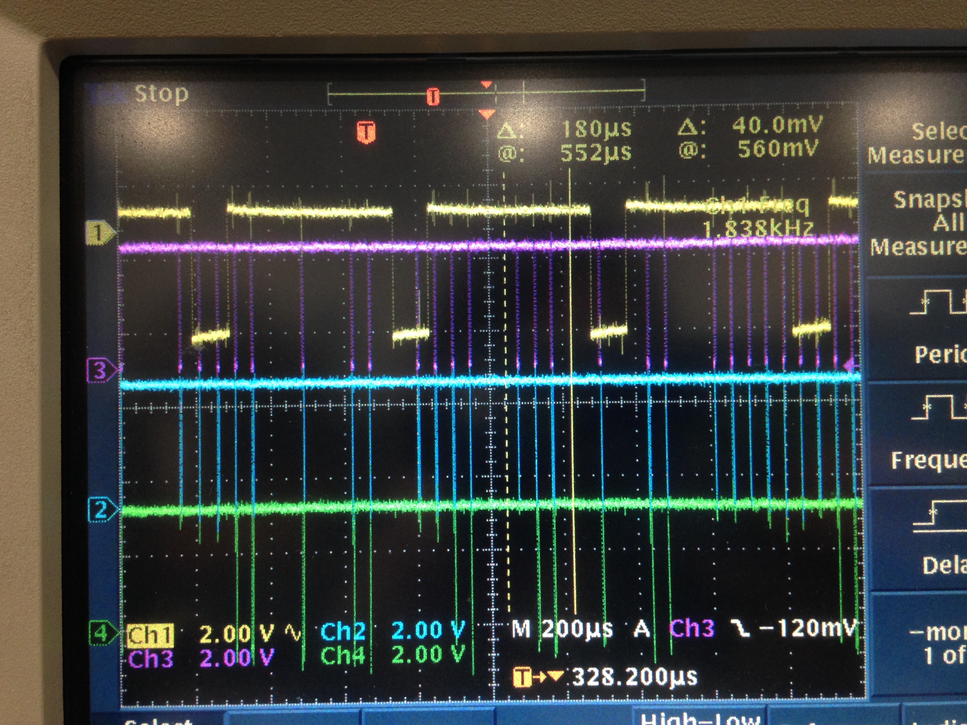
As you can see, from some of the periods, while the CSbar and clock are sent correctly, the SOMI signal, which is suppose to have a data, is still 0xFFFF.
In order to figure our where the problem is, I let SPIA just send data from an array with fixed values instead of what SPIB has read to:
//**************** Send data to BBB*****************
	Uint16 sdata[500];
	for (i = 0; i < 500; i++)
		sdata[i] = i;
	for(;;)
	{
	   readytxflag = 1;
	   if (readytxflag == 1)
	   {
		  for(i = 0; i < sizeof(sdata); i++)
		  {
                     SpiaRegs.SPITXBUF=sdata[i];
		     while(SpiaRegs.SPISTS.bit.INT_FLAG != 1) {}
		  }
	   }
	}
Part of the read value looks like
| 65535 |
| 193 |
| 65535 |
| 65535 |
| 194 |
| 65535 |
| 195 |
| 65535 |
| 65535 |
| 65535 |
| 65535 |
| 65535 |
| 65535 |
| 65535 |
| 65535 |
| 65535 |
| 65535 |
| 196 |
| 65535 |
| 65535 |
| 65535 |
| 65535 |
| 65535 |
| 65535 |
| 197 |
| 65535 |
| 65535 |
| 65535 |
| 65535 |
| 65535 |
| 65535 |
| 65535 |
| 65535 |
| 65535 |
As you can see, none of the data is missing, but there are 0xFFFF between them. I can tell Beaglebone to ignore the data if it is 0xFFFF, but it slows down the transmission rate significantly.
It looks like that the SpiaRegs.SPISTS.bit.INT_FLAG is not set fast enough so that before beaglebone reads the next data, the next data is not filled into SPITXBUF yet, thus SPITXBUF is feeding 0xFFFF into SPIDAT, which is transmitted over to Beagle bone. Thus we have tried other indicators such as SpiaRegs.SPIPRI.bit.STEINV and SpiaRegs.SPISTS.bit.BUFFULL_FLAG, they either does not work at all, or does not solve the problem.
We also have tried to feed into SPIDAT directly without going through SPITXBUF and fill in value and fill in the next value one all the bits in SPIDAT are shifted out:
for(i = 0; i < sizeof(sdata); i++)
   {
      SpiaRegs.SPIDAT=sdata[i];
      while(SpiaRegs.SPIDAT != 0xFFFF){}
   }
Then the data start to look better:
| 372 |
| 373 |
| 374 |
| 375 |
| 376 |
| 377 |
| 378 |
| 379 |
| 380 |
| 381 |
| 382 |
| 382 |
| 1539 |
| 385 |
| 386 |
| 387 |
| 388 |
| 389 |
| 390 |
| 391 |
| 392 |
| 393 |
| 394 |
| 395 |
| 396 |
But some data are not sent correctly (483 and 484 above), some other incorrect data looks like:
| 57 |
| 58 |
| 59 |
| 60 |
| 61 |
| 62 |
| 62 |
| 129 |
| 65 |
| 66 |
| 67 |
| 68 |
| 69 |
| 70 |
| 71 |
(63, 64)
| 120 |
| 121 |
| 122 |
| 123 |
| 124 |
| 125 |
| 126 |
| 124 |
| 515 |
| 129 |
| 130 |
| 131 |
| 132 |
| 133 |
| 134 |
| 135 |
(127, 128)
| 183 |
| 184 |
| 185 |
| 186 |
| 187 |
| 188 |
| 189 |
| 190 |
| 191 |
| 385 |
| 193 |
| 194 |
| 195 |
| 196 |
| 197 |
| 198 |
| 199 |
| 200 |
(192)
| 250 |
| 251 |
| 252 |
| 253 |
| 254 |
| 1 |
| 1 |
| 257 |
| 513 |
| 1023 |
| 260 |
| 261 |
| 262 |
| 263 |
| 264 |
| 265 |
| 266 |
(255, 256, 258, 259)
I have also tried to slow down the reading rates from the Beaglebone side, but the error percentage increased, looks like the data transmission make an error once per time period.
Any suggestions on how should I fix this slave transmitting problem so that I can read data with no error and no 0xFFFF between? Please let me know if there are any other info I can provide.
Thanks!
Yuqi