
- Ask a related questionWhat is a related question?A related question is a question created from another question. When the related question is created, it will be automatically linked to the original question.
Hi,
I am learning the piccolo series DSC with F28069 and working on the ADC temperature sensor conversion functions.
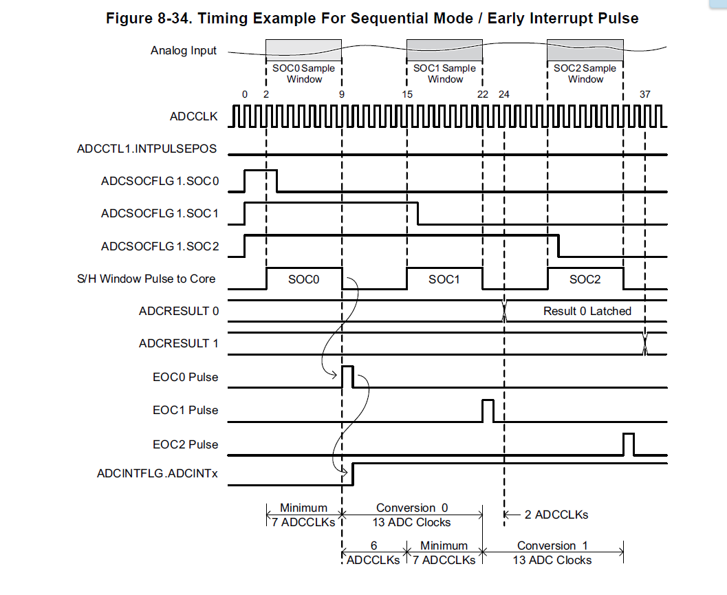
In the example, the completion of ADC sampling is judged by EOCx INT pulse and as shown below.
//Wait for end of conversion.
while(AdcRegs.ADCINTFLG.bit.ADCINT1 == 0){}  //Wait for ADCINT1
AdcRegs.ADCINTFLGCLR.bit.ADCINT1 = 1;        //Clear ADCINT1
But I looked at the ADC timing and found that the int pulse occurs much earlier than the point that the result is latched.
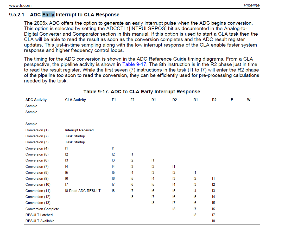
Then I referred to the CLA chapter and there is something about the ADC Early Interrupt to CLA Response. Then I know CLA can get the correct ADC result.
Does the C28x pipeline is the same with the CLA pipeline?
In the TMS320C28x Extended Instruction Sets Technical Reference Manual there is a figure about the C28x pipeline, it seems just the same as the CLA pipeline.
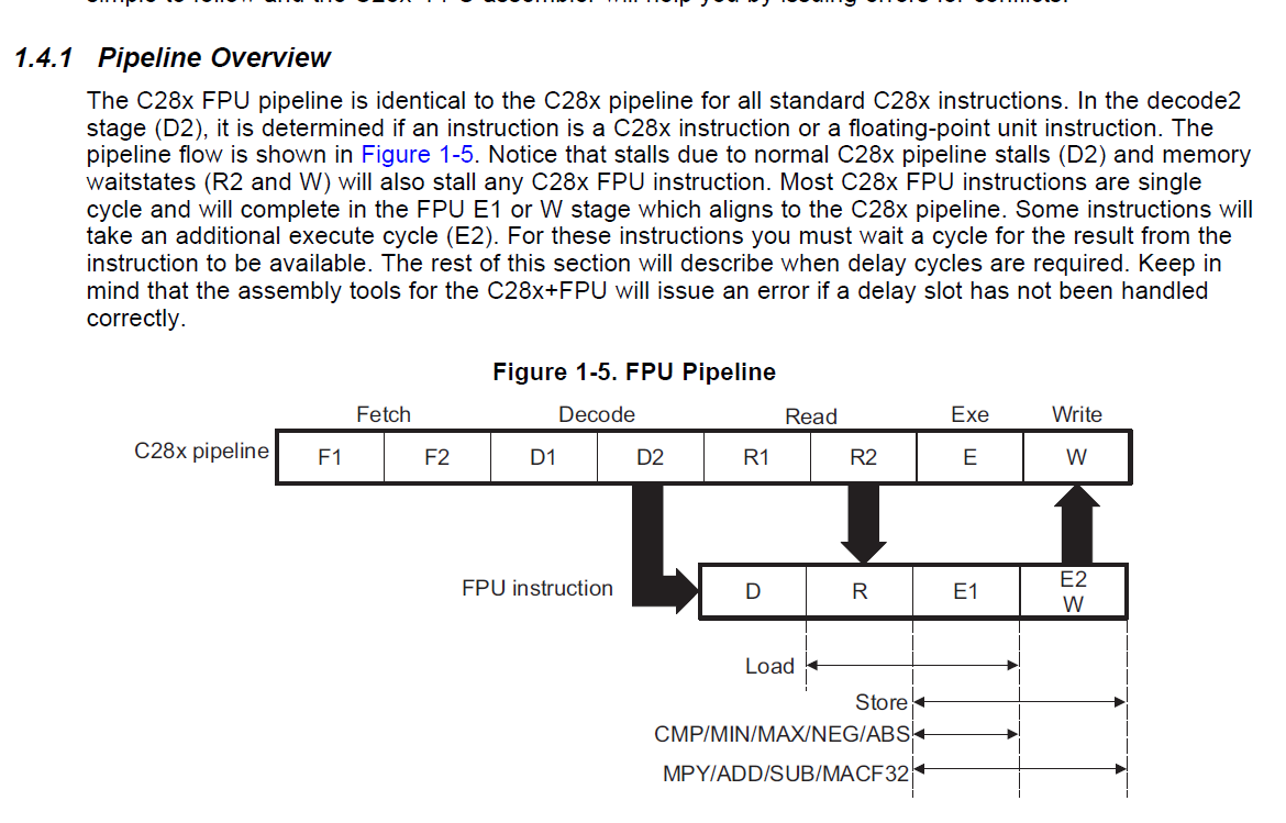
So can I just think they are the same and I can make sure that the result I read is a correct one?
thanks and regards
: )
-Di


