This thread has been locked.

If you have a related question, please click the "Ask a related question" button in the top right corner. The newly created question will be automatically linked to this question.

Downloading simple blinky program to a target board with TMS320F28379D, XDS100V2 and Code Composer 6.1.2.00015

Other Parts Discussed in Thread: TMS320F28379D, CONTROLSUITE, TMS320F28377D, TMDSCNCD28379D

Hi Everyone,

I am new to Code Composer and therefore having difficulty.

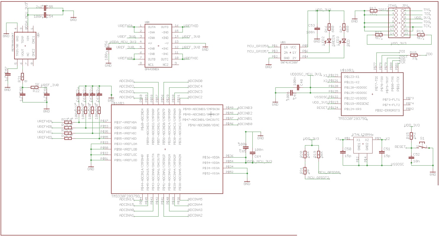
I have made a target board for TMS320F28379D based on the controlCARD R1.3. And I am using XDS100V2 14-pin JTAG Emulator/Debug probe with Code Composer 6.1.2.00015.

Following all instruction on how to connect the emulator to the target board I was able to test the connection successfully (see result below).

Next thing in the instructions was to "Launch Selected Configuration" and on doing that a debug session started and showed this:

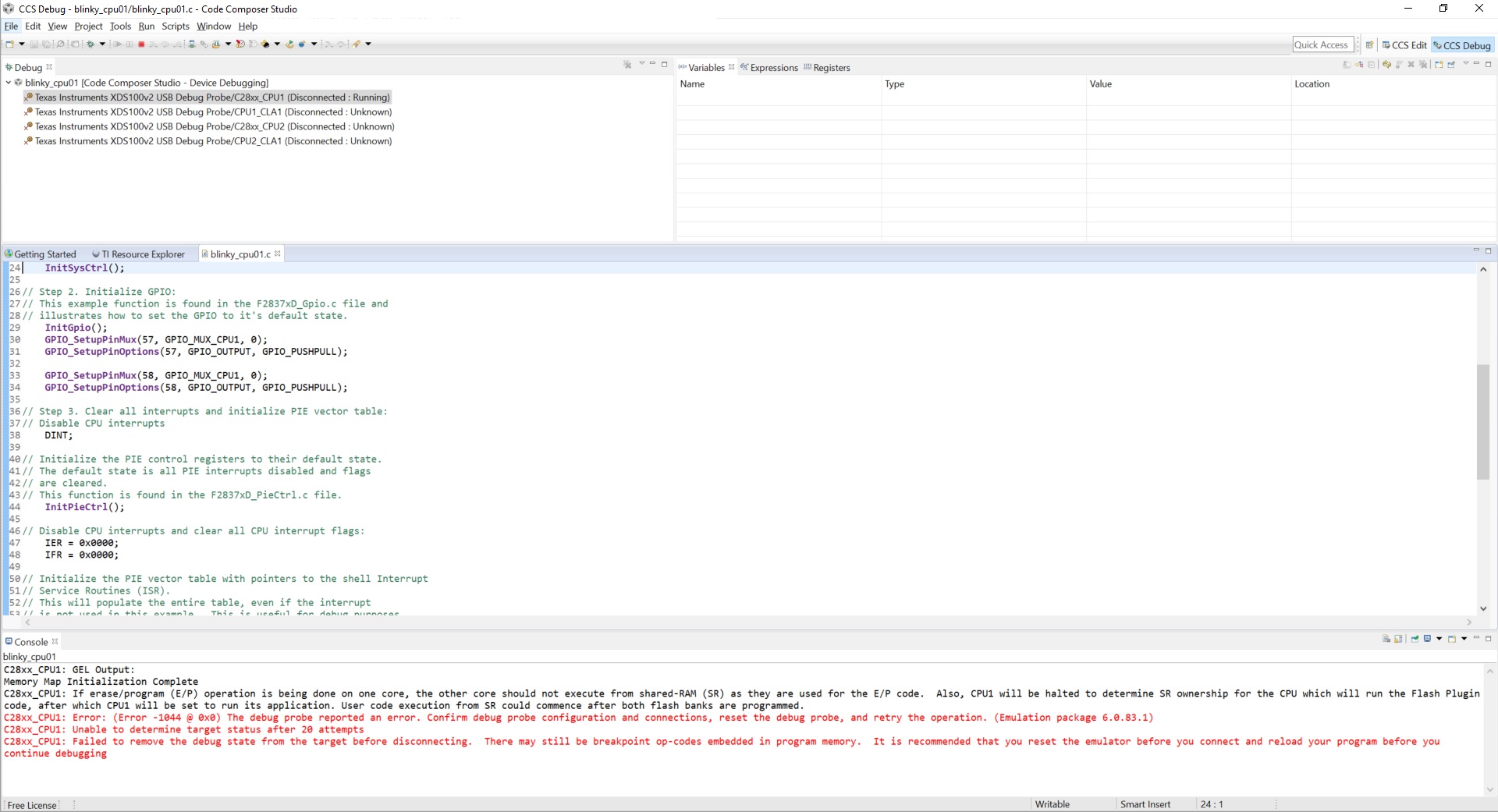
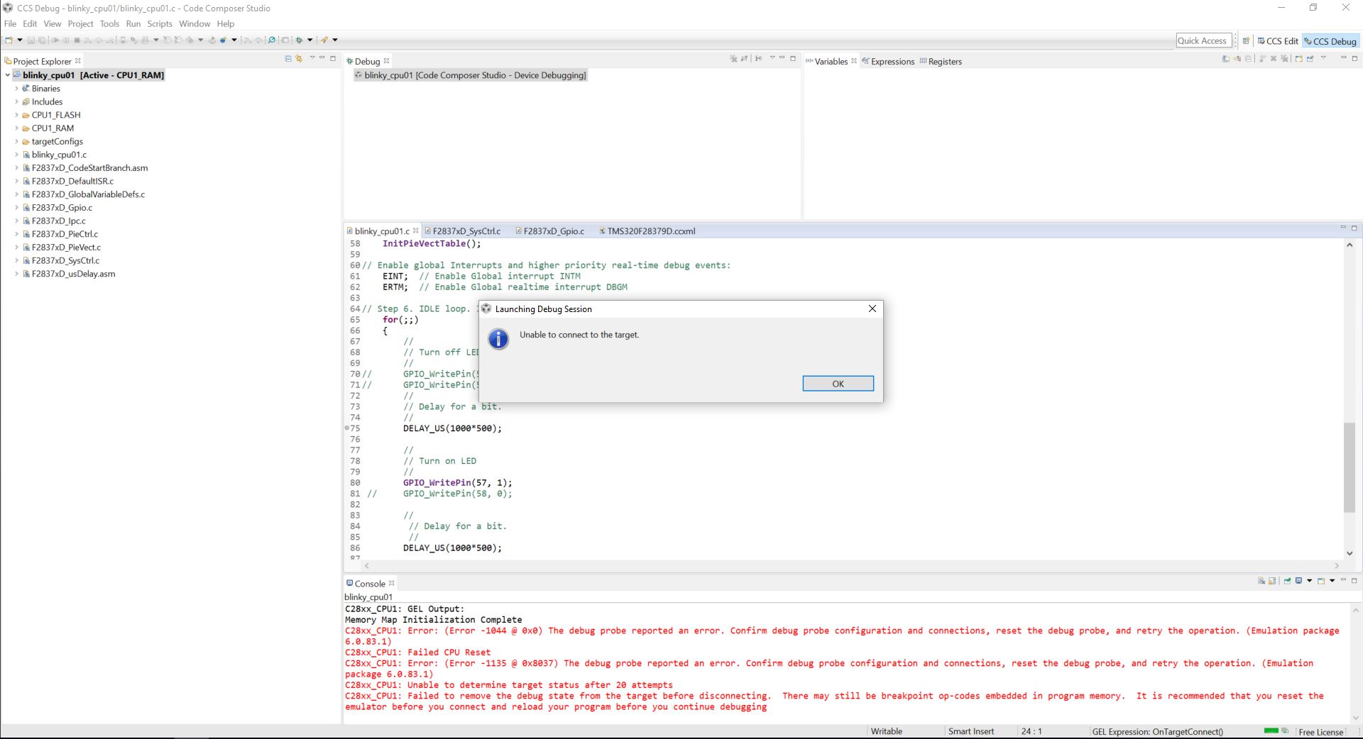
Since for all the cores it shows (Disconnected:Unknown), I right clicked each and was able to select "Connect Target" which resulted in the following:

I am using the default boot mode, that is, GPIO72 & 84 are pulled HIGH. I also have a RESET button connected to the XRS pin which is always HIGH and goes LOW when the button is pressed. The ERRORSTS pin is also LOW. I also made sure that there is continuity from the debugger on to my target board for the JTAG pins, nTRST pin goes HIGH when debug is launched otherwise it is LOW and TCK is 1MHz when the running connection test.

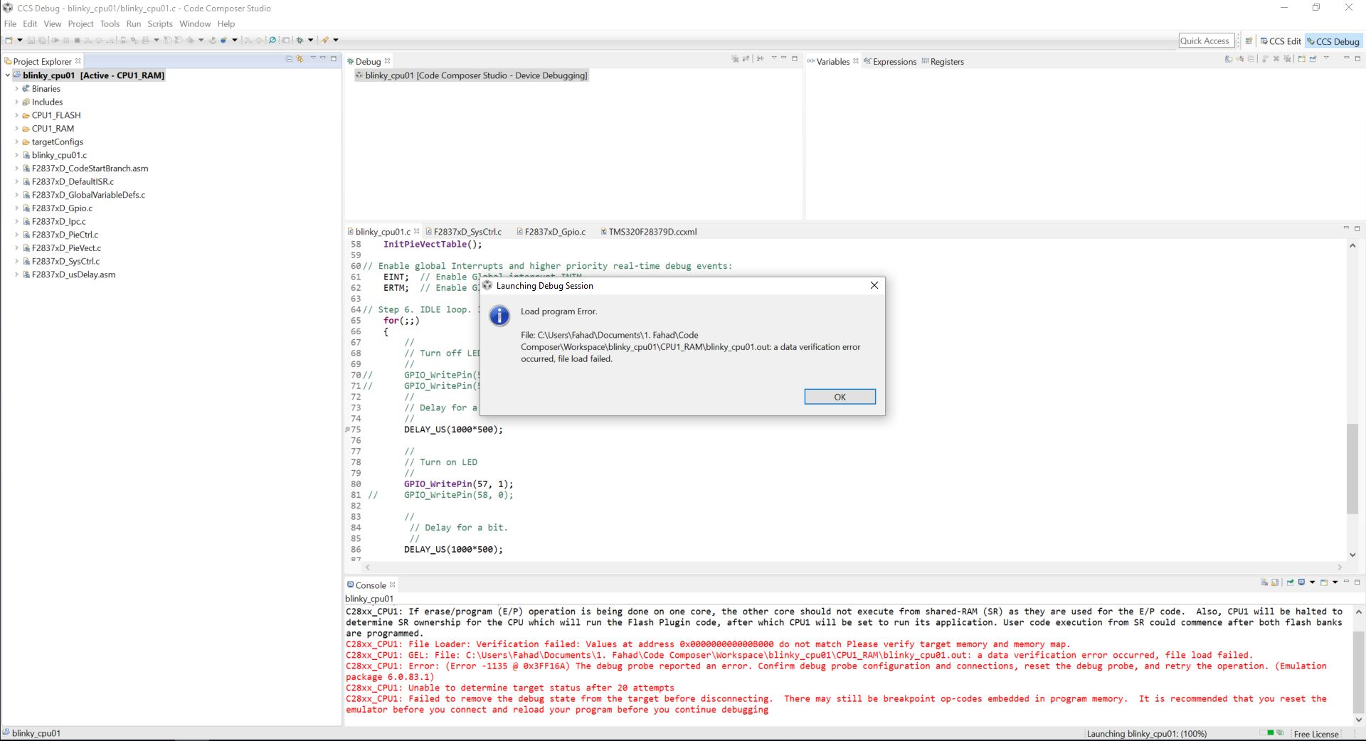
With all this done I want to now download a simple LED blink program of which there is an example in controlsuite. After loading that from controlsuite to the workspace I modified the properties of the project to use the MCU and debugger I am using. Here is what I changed:

Doing that created and made active a new TargetConfig file TMS320F28379D.ccxml. The original example had TMS320F28377D.ccxml. Now I clean/build the program resulting in 58 errors. They all seem to be Linker errors (see below). I have Set Active CPU1_RAM under Build Configuration as opposed to CPU1_FLASH. When I change to CPU1_Flash I get the same linker errors.

Can you please point me in the direction of how to go about fixing these errors?

Any help will be much appreciated.

Thank you for your quick response.

Fahad

===================================================JTAG CONNECTION TEST===================================================
[Start: Texas Instruments XDS100v2 USB Debug Probe_0]

Execute the command:

%ccs_base%/common/uscif/dbgjtag -f %boarddatafile% -rv -o -F inform,logfile=yes -S pathlength -S integrity

[Result]


-----[Print the board config pathname(s)]------------------------------------

C:\Users\Fahad\AppData\Local\TEXASI~1\CCS\
ti\0\0\BrdDat\testBoard.dat

-----[Print the reset-command software log-file]-----------------------------

This utility has selected a 100- or 510-class product.
This utility will load the adapter 'jioserdesusb.dll'.
The library build date was 'Dec 9 2015'.
The library build time was '20:05:50'.
The library package version is '6.0.83.1'.
The library component version is '35.35.0.0'.
The controller does not use a programmable FPGA.
The controller has a version number of '4' (0x00000004).
The controller has an insertion length of '0' (0x00000000).
This utility will attempt to reset the controller.
This utility has successfully reset the controller.

-----[Print the reset-command hardware log-file]-----------------------------

The scan-path will be reset by toggling the JTAG TRST signal.
The controller is the FTDI FT2232 with USB interface.
The link from controller to target is direct (without cable).
The software is configured for FTDI FT2232 features.
The controller cannot monitor the value on the EMU[0] pin.
The controller cannot monitor the value on the EMU[1] pin.
The controller cannot control the timing on output pins.
The controller cannot control the timing on input pins.
The scan-path link-delay has been set to exactly '0' (0x0000).

-----[The log-file for the JTAG TCLK output generated from the PLL]----------

There is no hardware for programming the JTAG TCLK frequency.

-----[Measure the source and frequency of the final JTAG TCLKR input]--------

There is no hardware for measuring the JTAG TCLK frequency.

-----[Perform the standard path-length test on the JTAG IR and DR]-----------

This path-length test uses blocks of 64 32-bit words.

The test for the JTAG IR instruction path-length succeeded.
The JTAG IR instruction path-length is 6 bits.

The test for the JTAG DR bypass path-length succeeded.
The JTAG DR bypass path-length is 1 bits.

-----[Perform the Integrity scan-test on the JTAG IR]------------------------

This test will use blocks of 64 32-bit words.
This test will be applied just once.

Do a test using 0xFFFFFFFF.
Scan tests: 1, skipped: 0, failed: 0
Do a test using 0x00000000.
Scan tests: 2, skipped: 0, failed: 0
Do a test using 0xFE03E0E2.
Scan tests: 3, skipped: 0, failed: 0
Do a test using 0x01FC1F1D.
Scan tests: 4, skipped: 0, failed: 0
Do a test using 0x5533CCAA.
Scan tests: 5, skipped: 0, failed: 0
Do a test using 0xAACC3355.
Scan tests: 6, skipped: 0, failed: 0
All of the values were scanned correctly.

The JTAG IR Integrity scan-test has succeeded.

-----[Perform the Integrity scan-test on the JTAG DR]------------------------

This test will use blocks of 64 32-bit words.
This test will be applied just once.

Do a test using 0xFFFFFFFF.
Scan tests: 1, skipped: 0, failed: 0
Do a test using 0x00000000.
Scan tests: 2, skipped: 0, failed: 0
Do a test using 0xFE03E0E2.
Scan tests: 3, skipped: 0, failed: 0
Do a test using 0x01FC1F1D.
Scan tests: 4, skipped: 0, failed: 0
Do a test using 0x5533CCAA.
Scan tests: 5, skipped: 0, failed: 0
Do a test using 0xAACC3355.
Scan tests: 6, skipped: 0, failed: 0
All of the values were scanned correctly.

The JTAG DR Integrity scan-test has succeeded.

[End: Texas Instruments XDS100v2 USB Debug Probe_0]
===================================================JTAG CONNECTION TEST===================================================

==================================================LINKER ERROR===========================================================
'Building target: blinky_cpu01.out'
'Invoking: C2000 Linker'
"C:/ti/ccsv6/tools/compiler/ti-cgt-c2000_6.4.10/bin/cl2000" -v28 -ml -mt --float_support=fpu32 --tmu_support=tmu0 --cla_support=cla1 --vcu_support=vcu2 -g --define=CPU1 --diag_warning=225 --display_error_number --diag_suppress=10063 -z -m"blinky_cpu01.map" --stack_size=0x100 --warn_sections -i"C:/ti/ccsv6/tools/compiler/ti-cgt-c2000_6.4.10/lib" -i"C:/ti/ccsv6/tools/compiler/ti-cgt-c2000_6.4.10/include" -i"C:/ti/controlSUITE/device_support/F2837xD/v190/F2837xD_common/cmd" -i"C:/ti/controlSUITE/device_support/F2837xD/v190/F2837xD_headers/cmd" --reread_libs --display_error_number --xml_link_info="blinky_cpu01_linkInfo.xml" --entry_point=code_start --rom_model -o "blinky_cpu01.out" "./F2837xD_CodeStartBranch.obj" "./F2837xD_DefaultISR.obj" "./F2837xD_GlobalVariableDefs.obj" "./F2837xD_Gpio.obj" "./F2837xD_Ipc.obj" "./F2837xD_PieCtrl.obj" "./F2837xD_PieVect.obj" "./F2837xD_SysCtrl.obj" "./F2837xD_usDelay.obj" "./blinky_cpu01.obj" "../2837x_FLASH_lnk_cpu1.cmd" -l"rts2800_fpu32.lib" -l"2837xD_RAM_lnk_cpu1.cmd" -l"F2837xD_Headers_nonBIOS_cpu1.cmd" -l"libc.a"
<Linking>
"C:/ti/controlSUITE/device_support/F2837xD/v190/F2837xD_common/cmd/2837xD_RAM_lnk_cpu1.cmd", line 7: error #10263:
BEGIN memory range has already been specified
"C:/ti/controlSUITE/device_support/F2837xD/v190/F2837xD_common/cmd/2837xD_RAM_lnk_cpu1.cmd", line 8: error #10263:
RAMM0 memory range has already been specified
"C:/ti/controlSUITE/device_support/F2837xD/v190/F2837xD_common/cmd/2837xD_RAM_lnk_cpu1.cmd", line 8: error #10264:
RAMM0 memory range overlaps existing memory range RAMM0
"C:/ti/controlSUITE/device_support/F2837xD/v190/F2837xD_common/cmd/2837xD_RAM_lnk_cpu1.cmd", line 9: error #10263:
RAMD0 memory range has already been specified
"C:/ti/controlSUITE/device_support/F2837xD/v190/F2837xD_common/cmd/2837xD_RAM_lnk_cpu1.cmd", line 9: error #10264:
RAMD0 memory range overlaps existing memory range RAMD0
"C:/ti/controlSUITE/device_support/F2837xD/v190/F2837xD_common/cmd/2837xD_RAM_lnk_cpu1.cmd", line 10: error #10263:
RAMLS0 memory range has already been specified
"C:/ti/controlSUITE/device_support/F2837xD/v190/F2837xD_common/cmd/2837xD_RAM_lnk_cpu1.cmd", line 10: error #10264:
RAMLS0 memory range overlaps existing memory range RAMLS0
"C:/ti/controlSUITE/device_support/F2837xD/v190/F2837xD_common/cmd/2837xD_RAM_lnk_cpu1.cmd", line 11: error #10263:
RAMLS1 memory range has already been specified
"C:/ti/controlSUITE/device_support/F2837xD/v190/F2837xD_common/cmd/2837xD_RAM_lnk_cpu1.cmd", line 11: error #10264:
RAMLS1 memory range overlaps existing memory range RAMLS1
"C:/ti/controlSUITE/device_support/F2837xD/v190/F2837xD_common/cmd/2837xD_RAM_lnk_cpu1.cmd", line 12: error #10263:
RAMLS2 memory range has already been specified
"C:/ti/controlSUITE/device_support/F2837xD/v190/F2837xD_common/cmd/2837xD_RAM_lnk_cpu1.cmd", line 12: error #10264:
RAMLS2 memory range overlaps existing memory range RAMLS2
"C:/ti/controlSUITE/device_support/F2837xD/v190/F2837xD_common/cmd/2837xD_RAM_lnk_cpu1.cmd", line 13: error #10263:
RAMLS3 memory range has already been specified
"C:/ti/controlSUITE/device_support/F2837xD/v190/F2837xD_common/cmd/2837xD_RAM_lnk_cpu1.cmd", line 13: error #10264:
RAMLS3 memory range overlaps existing memory range RAMLS3
"C:/ti/controlSUITE/device_support/F2837xD/v190/F2837xD_common/cmd/2837xD_RAM_lnk_cpu1.cmd", line 14: error #10263:
RAMLS4 memory range has already been specified
"C:/ti/controlSUITE/device_support/F2837xD/v190/F2837xD_common/cmd/2837xD_RAM_lnk_cpu1.cmd", line 14: error #10264:
RAMLS4 memory range overlaps existing memory range RAMLS4
"C:/ti/controlSUITE/device_support/F2837xD/v190/F2837xD_common/cmd/2837xD_RAM_lnk_cpu1.cmd", line 15: error #10263:
RESET memory range has already been specified
"C:/ti/controlSUITE/device_support/F2837xD/v190/F2837xD_common/cmd/2837xD_RAM_lnk_cpu1.cmd", line 15: error #10264:
RESET memory range overlaps existing memory range RESET
"C:/ti/controlSUITE/device_support/F2837xD/v190/F2837xD_common/cmd/2837xD_RAM_lnk_cpu1.cmd", line 19: error #10263:
BOOT_RSVD memory range has already been specified
"C:/ti/controlSUITE/device_support/F2837xD/v190/F2837xD_common/cmd/2837xD_RAM_lnk_cpu1.cmd", line 19: error #10264:
BOOT_RSVD memory range overlaps existing memory range BOOT_RSVD
"C:/ti/controlSUITE/device_support/F2837xD/v190/F2837xD_common/cmd/2837xD_RAM_lnk_cpu1.cmd", line 20: error #10263:
RAMM1 memory range has already been specified
"C:/ti/controlSUITE/device_support/F2837xD/v190/F2837xD_common/cmd/2837xD_RAM_lnk_cpu1.cmd", line 20: error #10264:
RAMM1 memory range overlaps existing memory range RAMM1
"C:/ti/controlSUITE/device_support/F2837xD/v190/F2837xD_common/cmd/2837xD_RAM_lnk_cpu1.cmd", line 21: error #10263:
RAMD1 memory range has already been specified
"C:/ti/controlSUITE/device_support/F2837xD/v190/F2837xD_common/cmd/2837xD_RAM_lnk_cpu1.cmd", line 21: error #10264:
RAMD1 memory range overlaps existing memory range RAMD1
"C:/ti/controlSUITE/device_support/F2837xD/v190/F2837xD_common/cmd/2837xD_RAM_lnk_cpu1.cmd", line 23: error #10263:
RAMLS5 memory range has already been specified
"C:/ti/controlSUITE/device_support/F2837xD/v190/F2837xD_common/cmd/2837xD_RAM_lnk_cpu1.cmd", line 23: error #10264:
RAMLS5 memory range overlaps existing memory range RAMLS5
"C:/ti/controlSUITE/device_support/F2837xD/v190/F2837xD_common/cmd/2837xD_RAM_lnk_cpu1.cmd", line 25: error #10263:
RAMGS0 memory range has already been specified
"C:/ti/controlSUITE/device_support/F2837xD/v190/F2837xD_common/cmd/2837xD_RAM_lnk_cpu1.cmd", line 25: error #10264:
RAMGS0 memory range overlaps existing memory range RAMGS0
"C:/ti/controlSUITE/device_support/F2837xD/v190/F2837xD_common/cmd/2837xD_RAM_lnk_cpu1.cmd", line 26: error #10263:
RAMGS1 memory range has already been specified
"C:/ti/controlSUITE/device_support/F2837xD/v190/F2837xD_common/cmd/2837xD_RAM_lnk_cpu1.cmd", line 26: error #10264:
RAMGS1 memory range overlaps existing memory range RAMGS1
"C:/ti/controlSUITE/device_support/F2837xD/v190/F2837xD_common/cmd/2837xD_RAM_lnk_cpu1.cmd", line 27: error #10263:
RAMGS2 memory range has already been specified
"C:/ti/controlSUITE/device_support/F2837xD/v190/F2837xD_common/cmd/2837xD_RAM_lnk_cpu1.cmd", line 27: error #10264:
RAMGS2 memory range overlaps existing memory range RAMGS2
"C:/ti/controlSUITE/device_support/F2837xD/v190/F2837xD_common/cmd/2837xD_RAM_lnk_cpu1.cmd", line 28: error #10263:
RAMGS3 memory range has already been specified
"C:/ti/controlSUITE/device_support/F2837xD/v190/F2837xD_common/cmd/2837xD_RAM_lnk_cpu1.cmd", line 28: error #10264:
RAMGS3 memory range overlaps existing memory range RAMGS3
"C:/ti/controlSUITE/device_support/F2837xD/v190/F2837xD_common/cmd/2837xD_RAM_lnk_cpu1.cmd", line 29: error #10263:
RAMGS4 memory range has already been specified
"C:/ti/controlSUITE/device_support/F2837xD/v190/F2837xD_common/cmd/2837xD_RAM_lnk_cpu1.cmd", line 29: error #10264:
RAMGS4 memory range overlaps existing memory range RAMGS4
"C:/ti/controlSUITE/device_support/F2837xD/v190/F2837xD_common/cmd/2837xD_RAM_lnk_cpu1.cmd", line 30: error #10263:
RAMGS5 memory range has already been specified
"C:/ti/controlSUITE/device_support/F2837xD/v190/F2837xD_common/cmd/2837xD_RAM_lnk_cpu1.cmd", line 30: error #10264:
RAMGS5 memory range overlaps existing memory range RAMGS5
"C:/ti/controlSUITE/device_support/F2837xD/v190/F2837xD_common/cmd/2837xD_RAM_lnk_cpu1.cmd", line 31: error #10263:
RAMGS6 memory range has already been specified
"C:/ti/controlSUITE/device_support/F2837xD/v190/F2837xD_common/cmd/2837xD_RAM_lnk_cpu1.cmd", line 31: error #10264:
RAMGS6 memory range overlaps existing memory range RAMGS6
"C:/ti/controlSUITE/device_support/F2837xD/v190/F2837xD_common/cmd/2837xD_RAM_lnk_cpu1.cmd", line 32: error #10263:
RAMGS7 memory range has already been specified
"C:/ti/controlSUITE/device_support/F2837xD/v190/F2837xD_common/cmd/2837xD_RAM_lnk_cpu1.cmd", line 32: error #10264:
RAMGS7 memory range overlaps existing memory range RAMGS7
"C:/ti/controlSUITE/device_support/F2837xD/v190/F2837xD_common/cmd/2837xD_RAM_lnk_cpu1.cmd", line 33: error #10263:
RAMGS8 memory range has already been specified
"C:/ti/controlSUITE/device_support/F2837xD/v190/F2837xD_common/cmd/2837xD_RAM_lnk_cpu1.cmd", line 33: error #10264:
RAMGS8 memory range overlaps existing memory range RAMGS8
"C:/ti/controlSUITE/device_support/F2837xD/v190/F2837xD_common/cmd/2837xD_RAM_lnk_cpu1.cmd", line 34: error #10263:
RAMGS9 memory range has already been specified
"C:/ti/controlSUITE/device_support/F2837xD/v190/F2837xD_common/cmd/2837xD_RAM_lnk_cpu1.cmd", line 34: error #10264:
RAMGS9 memory range overlaps existing memory range RAMGS9
"C:/ti/controlSUITE/device_support/F2837xD/v190/F2837xD_common/cmd/2837xD_RAM_lnk_cpu1.cmd", line 35: error #10263:
RAMGS10 memory range has already been specified
"C:/ti/controlSUITE/device_support/F2837xD/v190/F2837xD_common/cmd/2837xD_RAM_lnk_cpu1.cmd", line 35: error #10264:
RAMGS10 memory range overlaps existing memory range RAMGS10
"C:/ti/controlSUITE/device_support/F2837xD/v190/F2837xD_common/cmd/2837xD_RAM_lnk_cpu1.cmd", line 36: error #10263:
RAMGS11 memory range has already been specified
"C:/ti/controlSUITE/device_support/F2837xD/v190/F2837xD_common/cmd/2837xD_RAM_lnk_cpu1.cmd", line 36: error #10264:
RAMGS11 memory range overlaps existing memory range RAMGS11

"C:/ti/controlSUITE/device_support/F2837xD/v190/F2837xD_common/cmd/2837xD_RAM_lnk_cpu1.cmd", line 37: error #10263:
>> Compilation failure
RAMGS12 memory range has already been specified
"C:/ti/controlSUITE/device_support/F2837xD/v190/F2837xD_common/cmd/2837xD_RAM_lnk_cpu1.cmd", line 37: error #10264:
RAMGS12 memory range overlaps existing memory range RAMGS12
"C:/ti/controlSUITE/device_support/F2837xD/v190/F2837xD_common/cmd/2837xD_RAM_lnk_cpu1.cmd", line 38: error #10263:
RAMGS13 memory range has already been specified
"C:/ti/controlSUITE/device_support/F2837xD/v190/F2837xD_common/cmd/2837xD_RAM_lnk_cpu1.cmd", line 38: error #10264:
RAMGS13 memory range overlaps existing memory range RAMGS13
"C:/ti/controlSUITE/device_support/F2837xD/v190/F2837xD_common/cmd/2837xD_RAM_lnk_cpu1.cmd", line 42: error #10263:
CPU2TOCPU1RAM memory range has already been specified
"C:/ti/controlSUITE/device_support/F2837xD/v190/F2837xD_common/cmd/2837xD_RAM_lnk_cpu1.cmd", line 42: error #10264:
CPU2TOCPU1RAM memory range overlaps existing memory range CPU2TOCPU1RAM
"C:/ti/controlSUITE/device_support/F2837xD/v190/F2837xD_common/cmd/2837xD_RAM_lnk_cpu1.cmd", line 43: error #10263:
CPU1TOCPU2RAM memory range has already been specified
"C:/ti/controlSUITE/device_support/F2837xD/v190/F2837xD_common/cmd/2837xD_RAM_lnk_cpu1.cmd", line 43: error #10264:
CPU1TOCPU2RAM memory range overlaps existing memory range CPU1TOCPU2RAM
error #10010: errors encountered during linking; "blinky_cpu01.out" not built
gmake: *** [blinky_cpu01.out] Error 1
gmake: Target `all' not remade because of errors.

**** Build Finished ****
==================================================LINKER ERROR===========================================================

  • Fahad,

    I think you have two linker command files added in your project.  In the below image, don't select any linker command file (select none) and see if that clears it up.

    Thanks and regards,

    Vamsi

  • Hi Fahad,

    Could you try compiling the project from controlSUITE without any modification and see if that works fine.

    Regards,
    Vivek Singh
  • Hi Vivek,

    I removed the blinky_cpu01 project from my workspace. Imported it  again from controlSuite and did a clean/build-all without making any changes or modification and got NO errors.

    The only changes in the properties of blinky_cpu01 example project I made was to specify the device and debugger I am using.

    For them connection test, it seems there is connection between the debugger and the target board. 

    What else can I do?

    Thanks for your reply. 

    Fahad

  • Hi Vamsi,

    Thank you for your reply.

    I made the linker file to be <none> and ended up getting NOerrors for both  Build Configurations CPU1_RAM and CPU1_Flash. When I click debug for either case, I am asked which CPU I want the program to be loaded into, CPU1 or CPU2. I chose CPU1 as it is the master.

    For CPU1_RAM configuration it seems that the program has loaded and stopped at the first line/breakpoint, waiting to RESUME. Here is what is looks like before pressing RESUME:

    After I press RESUME I get errors:

    Therefore, I stopped it and tried CPU_Flash. That too resulted in errors:

    I have checked all the power pins on the device and they have the required 3.3V or 1.2V.

    What else can I check?

    Thanks for your help

    Fahad

  • Here is the complete error I get with CPU_Flash configuration:

    C28xx_CPU1: Trouble Writing Memory Block at 0x50024 on Page 1 of Length 0x2: (Error -1044 @ 0x0) The debug probe reported an error. Confirm debug probe configuration and connections, reset the debug probe, and retry the operation. (Emulation package 6.0.83.1)
    C28xx_CPU1: Error occurred during flash operation: Target failed to write 0x00050024@Data
    C28xx_CPU1: Flash Programmer: Unable to acquire the pump semaphore. The other core might still be accessing the pump registers. Operation Cancelled.
    C28xx_CPU1: File Loader: Memory write failed: Unknown error
    C28xx_CPU1: GEL: File: C:\Users\Fahad\Documents\1. Fahad\Code Composer\Workspase\blinky_cpu01\CPU1_FLASH\blinky_cpu01.out: Load failed.
    C28xx_CPU1: Trouble Reading Register PC: (Error -1044 @ 0x0) The debug probe reported an error. Confirm debug probe configuration and connections, reset the debug probe, and retry the operation. (Emulation package 6.0.83.1)
    C28xx_CPU1: Error occurred during flash operation: Target failed to read register PC
    C28xx_CPU1: Trouble Writing Memory Block at 0x5f800 on Page 1 of Length 0x2: (Error -1044 @ 0x0) The debug probe reported an error. Confirm debug probe configuration and connections, reset the debug probe, and retry the operation. (Emulation package 6.0.83.1)
    C28xx_CPU1: Error occurred during flash operation: Target failed to write 0x0005F800@Data
    C28xx_CPU1: Trouble Writing Memory Block at 0x0 on Page 0 of Length 0x2: (Error -1044 @ 0x0) The debug probe reported an error. Confirm debug probe configuration and connections, reset the debug probe, and retry the operation. (Emulation package 6.0.83.1)
    C28xx_CPU1: Error occurred during flash operation: Target failed to write 0x00000@Program
    C28xx_CPU1: Trouble Setting Breakpoint with the Action "Remain Halted" at 0xc0e3: (Error -1044 @ 0x0) The debug probe reported an error. Confirm debug probe configuration and connections, reset the debug probe, and retry the operation. (Emulation package 6.0.83.1)
    C28xx_CPU1: Breakpoint Manager: Retrying with a AET breakpoint
    C28xx_CPU1: Breakpoint Manager: Error enabling this function: DCU_SEL Register write failed
    C28xx_CPU1: Error occurred during flash operation: Internal error while writing 0x0005F444@Data
    C28xx_CPU1: Error setting the GSxMSEL register for Flash operations
    C28xx_CPU1: Can't Run Target CPU: (Error -1044 @ 0x0) The debug probe reported an error. Confirm debug probe configuration and connections, reset the debug probe, and retry the operation. (Emulation package 6.0.83.1)
    C28xx_CPU1: Error: (Error -1044 @ 0x0) The debug probe reported an error. Confirm debug probe configuration and connections, reset the debug probe, and retry the operation. (Emulation package 6.0.83.1)
    C28xx_CPU1: Unable to determine target status after 20 attempts
    C28xx_CPU1: Failed to remove the debug state from the target before disconnecting. There may still be breakpoint op-codes embedded in program memory. It is recommended that you reset the emulator before you connect and reload your program before you continue debugging
    C28xx_CPU1: Error occurred during flash operation: Could not read 0x0007026D@Data: target is not connected
    C28xx_CPU1: Error occurred during flash operation: Could not write 0x0005F444@Data: target is not connected
    C28xx_CPU1: Error occurred during flash operation: Could not read 0x0005F444@Data: target is not connected
    C28xx_CPU1: Error setting the GSxMSEL register for Flash operations
    C28xx_CPU1: Error occurred during flash operation: Could not read 0x0007026D@Data: target is not connected
    C28xx_CPU1: Error occurred during flash operation: Could not write 0x0005D200@Data: target is not connected
    C28xx_CPU1: Error occurred during flash operation: Could not read 0x5D200@Program: target is not connected
    C28xx_CPU1: Error occurred during flash operation: Could not read 0x0007026D@Data: target is not connected
    C28xx_CPU1: Error occurred during flash operation: Could not read 0x0005D20E@Data: target is not connected
    C28xx_CPU1: Error occurred during flash operation: Could not write 0x0005D20E@Data: target is not connected
    C28xx_CPU1: Error occurred during flash operation: Could not read 0x0005D20E@Data: target is not connected
    C28xx_CPU1: Error occurred during flash operation: Could not write 0x0005D20E@Data: target is not connected
    C28xx_CPU1: Error occurred during flash operation: Could not read 0x0005D22E@Data: target is not connected
    C28xx_CPU1: Error occurred during flash operation: Could not read 0x0005D208@Data: target is not connected
    C28xx_CPU1: Error occurred during flash operation: Could not write 0x0005D208@Data: target is not connected
    C28xx_CPU1: Error occurred during flash operation: Could not read 0x0005D208@Data: target is not connected
    C28xx_CPU1: Error occurred during flash operation: Could not write 0x0005D208@Data: target is not connected
    C28xx_CPU1: Error occurred during flash operation: Could not read 0x0005D222@Data: target is not connected
    C28xx_CPU1: Error occurred during flash operation: Could not write 0x0005D222@Data: target is not connected
    C28xx_CPU1: Error occurred during flash operation: Could not write 0x0005D214@Data: target is not connected
    C28xx_CPU1: Error occurred during flash operation: Could not read 0x0005D20E@Data: target is not connected
    C28xx_CPU1: Error occurred during flash operation: Could not write 0x0005D20E@Data: target is not connected
    C28xx_CPU1: Error occurred during flash operation: Could not write 0x0005D20E@Data: target is not connected
    C28xx_CPU1: Error occurred during flash operation: Could not write 0x0005D222@Data: target is not connected
    C28xx_CPU1: Error occurred during flash operation: Could not write 0x0005D200@Data: target is not connected
    C28xx_CPU1: Error occurred during flash operation: Could not write 0x00000@Program: target is not connected
    C28xx_CPU1: Error occurred during flash operation: Cannot enable while the target is disconnected
    C28xx_CPU1: Error occurred during flash operation: Could not read 0x0005F444@Data: target is not connected
    C28xx_CPU1: Error occurred during flash operation: Could not read 0x0007026D@Data: target is not connected
    C28xx_CPU1: Error occurred during flash operation: Could not write 0x0005F444@Data: target is not connected
    C28xx_CPU1: Error occurred during flash operation: Could not read 0x0005F444@Data: target is not connected
    C28xx_CPU1: Error occurred during flash operation: Failed to run target while trying to execute pwrite_dis.alg
    C28xx_CPU1: Flash operation timed out waiting for the algorithm to complete. Operation cancelled.
    C28xx_CPU1: Error occurred during flash operation: Could not read 0x0007026D@Data: target is not connected
    C28xx_CPU1: Error occurred during flash operation: Could not write 0x0005F444@Data: target is not connected
    C28xx_CPU1: Error occurred during flash operation: Could not read 0x0005F444@Data: target is not connected
    C28xx_CPU1: Error occurred during flash operation: Could not write register PC: target is not connected

    Thanks
    Fahad
  • Fahad can you try with any other example. It seems you've overwritten to this sample code. This time when you import the project -> tick on "Copy to workspace" so that you can avoid this overwriting. Just check... If still you get the errors -> we'll have to check the project-> properties window for include paths etc.

    Regards,
    Gautam
  • Hi Gautum,

    Thanks for your reply.

    I imported the adc_soc_epwm_cpu01 example from controlSuite.

    Just like before, in the general section under properties I specified the target device to be TMS320F28379D and the connection to be TI XDS100v2 USB Debug Probe. This created the targetConfigs TMS320F28379D.ccxml. I also chose <none> for the linker command file, as Vamsi mentioned. Building it in both CPU1_RAM and CPU1_Flash gave no errors. However, when I ran DEBUG, I received the same errors as what I got for the blinky_cpu01 project.

    Do you suggest re-downloading controlSuite?

    Thanks again
    Fahad
  • Seems like a weird scenario! I'm not sure what is happening over here. You seem to get lot of linker errors and I somewhat have a doubt on the cmd file imported with the project.
  • Hi Guys,

    Linker errors were removed once I chose <none> for the linker command file.

    I have tried reinstalling control suite and code composer studio v6 , however, the problem remains. I even tried using a colleagues PC on which he is successfully connected to and is working with C2000 F28377S LaunchPad. We get the same errors during flash operation, that the target is not connected, target running on low power mode, try using slower TCLK, reset target and debugger etc..Which is weird because the JTAG test connection succeeds. PD pin is 3.3V, nTRST is HIGH when debugger is ON, otherwise it is low. TCLK is 1MHz, all power pins of the MCU is 3.3V and 1.2V as required. GPIO72 & 84 are pulled up for Get Mode Boot mode. VREFHIA-D are 3.0V using the same reference IC as on TMDSCNCD28379D R1.3.

    I do not see anything wrong on my target board, however, just for sanity check below is its schematic for your perusal, maybe you can find something that is not correct. The design is based on the experimenter kit TMDSCNCD28379D R1.3, therefore all the components are identical.  All the GPIOs are pulled out to be connected externally to control anything else, meaning these are the only connections.

    Please let me know if anything else comes to your mind that needs to be checked. 

    In the mean time I am ordering another XDS100V2 to rule out debugger problems.

  • Fahad,

    Did you notice below highlighted note from data manual (6.10 Boot ROM and Peripheral Booting @ www.ti.com/.../tms320f28377d.pdf)  

    The default behavior of Get mode is boot-to-flash. On unprogrammed devices, using Get mode will result in repeated watchdog resets, which may prevent proper JTAG connection and device initialization. Use Wait mode or another boot mode for unprogrammed devices.

    Try using wait boot mode.  

    Also, check for updates in CCS and install the updates (at least the ones from TI C2000 Device Support, Debug server Flash and Emulator packages).

    Our schematic expert is taking a look at your schematics. 

    Thanks and regards,

    Vamsi 

  • Hi Vamsi,

    I removed R19 and wired GPIO84 to GND to change the BOOT MODE to WAIT BOOT MODE. That too did not make a difference. The errors are the same.

    I just checked if there are any updates for CCS and it shows no updates available, therefore, all were installed.

    As I mentioned, I am new to using CCS, maybe I am missing a setting. Is there a step by step guide for CCS, other than the basic one?

    My colleague who is working with the C2000 F28377S LaunchPad, did not have to change the properties of the projects to indicate device or connection. Maybe because the examples are by default for F28377S.

    Fahad
  • Fahad,

    This is a 176-pin package. I checked Power, JTAG, Clocking and Reset – did not see any problems,

    Regards,
    PEter

  • Thank you Peter. I can for now rule out hardware issue :).
  • Fahad,

    There is no need to change the device variant in the project properties once you import the project from Controlsuite. Projects are setup as generic C28x projects and hence project properties should not be changed. Examples provided in F2837xD device support folder should have no issues running on F28379D.

    Once you import the project, just make sure to delete the TMS320F28377D.ccxml (right click on the ccxml file in the Project Explorer window and click on delete) and add the new target configuration file for F28379D (right click on the project -> New -> Target configuration file). No need to modify any project properties.

    Thanks and regards,
    Vamsi
  • Hi Vamsi,

    Thank you for your help with CCS. By doing what you suggested things started to work, a little :).

    What I noticed during CPU1_RAM that the code was downloaded and I can step through it (F5), however, when I ran, it crashed. Therefore, I went through the steps and found the place of the crash to be  inside InitPeripheralClocks(). For this test program I do not need any peripherals so I commented it out. By doing that the program ran like a beauty for few seconds and then crashed, however, with breakpoints in the for loop of main(), I am able to run for ever. This was all in CPU1_RAM build.

    Next I tried CPU1_FLASH build. Again without  InitPeripheralClocks(). I was able to program the MCU on one target board with USB power and another with a Power Supply. The reason I used two different power source was to see if the Dual output LDO (same as the Experimenter Kit) is receiving enough operating power. With the program running the consumed current by the target board was 110mA.

    Now is where I run into more problems. Downloading again a modified example of blinky, in either CPU1_RAM or CPU1_FLASH is not working. For CPU1_RAM I get:

    and for CPU1_FLASH I get:

    I monitored the nTRST JTAG pin. It went from LOW to HIGH and downloading crashed. Before downloading I ran the Connection Test and it too succeeded. 

    I am pretty sure this MCU is not one time programmable only, right??

    Another thing I noticed between the two identical target boards is that during debug on one I can see all cores of the MCU whereas on the other I see only CPU1. Selecting "show all cores" does not do anything either.

    The program that got flashed is running without any issues. Pressing the reset button, resets the MCU and the program restarts after the button is released.

    I know removing the InitPeripheralClocks() is not a solution as it will be needed later. 

    Any suggestions on what could be happening??

    Thanks for all your help.

    Fahad

  • Hi all,

    Changing to WAIT MODE has solved the repeat flashing issue.

    However, when InitPeripheralClocks() is added back into the code, I get the "operating in low power mode" error for both CPU1_RAM and CPU1_FLASH.

    Can this be because of the Dual-LDO not providing enough power to the MCU??.

    This Dual-LDO along with all its required external components are same the ones used in the Experimenter Kit TMDSCNCD28377D_R1_3.

    Thanks
    Fahad
  • Hi Fahad,

    I think it is possible that the reset could be from the device being current starved. Can you place a scope probe on the 5.0V, 3.3V, and 1.2V rails, as well as on the XRSn pin (trigger) while running the code?

    What is the value of the XTAL that you use in the circuit? Is it XTAL1 - 20MHz, or XTAL - 120MHz? I assume 20MHz. Have you checked the PLL settings to ensure that the device is running at 200MHz? You can also configure, and then check, the XCLKOUT pin.

    Is it possible that the "EDIS" instruction at the end of the InitPeripheralClocks() function is causing some other setting write to be missed somewhere else in the code after the function call?
  • Hi Devin,

    Thank you for your reply.

    The PLL is configured to 200MHz: InitSysPll(XTAL_OSC,IMULT_20,FMULT_0,PLLCLK_BY_2); with XTAL = 20MHz.

    So, I bypassed the LDO and now have 3.3V and 1.2V coming from a power supply. EVERYTHING is working the way it should :). Even with InitPeripheralClocks() function.

    My blinky is simple two LEDs alternating ON and OFF. See pics below. First one is Voltage settings, second shows the current. What I notice is pretty HIGH current from the 1.2V supply. 240mA is it supposed to be that HIGH??

    In any case, the LDO was not able to handle this. The Experimenter Kit uses the same LDO. Maybe my PCB design needs redoing or use separate LDOs for 3.3V and 1.2V.

    Thanks everyone for all your help.

    Fahad