This thread has been locked.

If you have a related question, please click the "Ask a related question" button in the top right corner. The newly created question will be automatically linked to this question.

CCS/TMS320F28027: Piccolo HVPSFB Peak Current Mode Control (PCMC) Zero Output possible

Part Number: TMS320F28027
Other Parts Discussed in Thread: CONTROLSUITE

Tool/software: Code Composer Studio

Dear Ti community,

I'm develop a peak current mode control on a phase shifted full bridge. My configuration for EPwm1 & EPwm2 is nearly the same as on the HVPSFB evaluation board software. Also the principle for the phase modification depanding on the comparator output is the same.

Through my understanding it is not possible that at a set value iref = 0 the phase of the two pwms is exactly zero. => When i set the set value iref = 0, i have a little overlap of the diagonal switches and the output 
on the secondary side of the transformer is not zero.

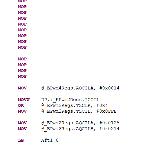
Because the Action Qualifier Register of EPwm2 toggle at zero between NOTHING and FORCE TO ZERO.

Is my understanding right?

Thank you for your answer,

Best regards
Tobias


  • Tooday, i've tested the original HVPSFB_PCMC software in the ControlSuite package, there is the same issue at a set value iref = 0.

    There is a little overlap between the both lowside switches.

    Yellow:  passive active low side switch


    Blue:     passive active low side switch

    Pink:     primary current

    Green   comparator output

    Iref = 0:

    Iref change works fine:

    Best regards

    Tobias

  • No ideas?

    Or has nobody the same Problem?

  • Hi Tobias,

    I am sorry for the delay. What you are seeing is expected behavior. As you stated, when iref = 0, there should ideally be no overlap between diagonal switches. However, this project also uses some blanking window to avoid leading edge noise. As a result, you will see some overlap between diagonal switches even when iref is 0.

    Hrishi

  • Hi Hrishi,

    thank you very much for your apply, so with the HVPSFB_PCMC software implementation there is a zero primary current not achievable? 

    What is the meaning of the blanking offset of two? Why is the offset not zero?

    I do not need the secondary synchronous rectification, so is there a other timer configuration of epwm1 & epwm2 submodule more suitable for PCMC?


    Best regards

    Tobias Ofenberger

  • Hi,

    The offset value decides the start of the blanking window. A value of 2 implies that the blanking window will start 2 clock cycles after the CTR = 0/PRD event of the PWM time-base. The offset value can be 0.

    The synchronous rectifiers in this project can operate in mode 0, where only body diodes are used for rectification. This is close to what you want to do. PWM1 and PWM2 configurations do not change when sync rectifiers are not used. There is code inside the assembly ISR that can be removed in this case. However, you have to preserve the code execution timing for different sections of the code (inside this ISR) for proper converter operation.

    I hope this helps.

    Hrishi

  • Hi,

    thank you very much,

    one last question:

    in the interrupt sevice rountine is at the beginning the following code:

    Is that for reloading the slope ramp?

    When yes why is it nessasery? in my opinion the ramp is reloaded with EPWm3 and with the comparator?

    Best regards,

    Tobias 

  • You are right, reloading of slope comp is done by the PWM3 trigger. However, the value that is loaded for the DAC output is the previous peak current reference. The new DAC value may not take effect till later in the present PWM cycle. I added these instructions here just to make sure that the DAC output starts moving towards the new peak current reference value as soon as possible. This is useful for better dynamic performance in case of big jumps in peak reference current.

    Hrishi

  • Ok, thank you very much for the fast reply,

    to sum up:

    The DAC slope ramp is reloaded every SYNC signal of EPwm3 and by a DAC SYNC event.
    In addition to get better dynamic performance it updates every entry in the EPwm1 interrupt service routine.
    I'm right?

    Best regards
    Tobias
  • Yes that is correct.
  • Thank you very much for your support!

  • Sorry but i have one more question:

    In my point of view has a TripZone event change during the blanking window time no effect on the event. In the PSFB PCMC example code with a deadband of 20 results a blanking windows time of 23 and a offset of 2. So a TripZone Event change during the TBCTR > 2 and TBCTR < 23 has no effect. But in the ISR is the TZCLR command in the blanking windwow time. What is the impact of this command?

    During the NOP's is the TBCTR == 0 expected, so the TZCLR command is definitly in the blanking window time.

    Thank you very much!

    Best regards

    Tobias