


Tool/software: Code Composer Studio
Hi,
I have been evaluation the instaSPIN platform with the DRV8301-69M-KIT (with F28069M/F control card) and adapted that design to a non-commercial own design, except it uses the TMS320F28027F. The partly assembled board with the 3V3 voltage and XDS100V2 debugger connected is pictured below. Currently the board has only the necessary component placement for flashing and debugging testing where I'm stuck at the moment.

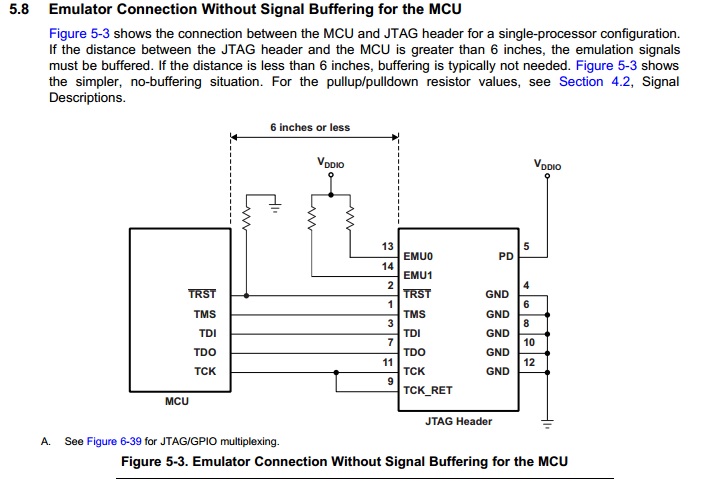
I have attached below the schematic from EAGLEcad, which shows the connections between the MCU and the debugger and the part from the "SPRS523K" document on what the connection is based on.

The real problem is that as a newcomer to the CCS, I'm still a bit lost around in it when it comes to making new target configurations and flashing bare bones MCUs. First problem is that I created a new target configuration for the XDS100v2 usb probe, but couldn't actually find the F28027F MCU on the device list. Only the F28027 or F280270. I did see the M and F variants for the F28052/54 MCUs, so I'm not sure if my target device is even correct.
Then as I try to debug the board with the lab_10a exercise from motorware for the drv8301kit using a f2802xF, just to try flashing the MCU (It's not going to do anything of sense of course as my schematic is different). But just work as a hello world for the flashing and debugging. As I try to debug I get the plethora of warning messages shown in the picture below. Which shows that I have the wrong device selected and for some reason the MCU is held in reset.

Hopefully with this info we can start to figure out how to solve this

