Part Number: TMS320F28379D
Other Parts Discussed in Thread: C2000WARE
Hi,
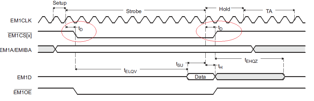
In the TRM, chapter 25.4.2.2 Configuring the Flash Interface provides an example to configure the EMIF register to interface SHARP LH28F800BJE-PTTL90 8Mb Flash memory with a clock frequency of fEM1CLK = 100 MHz. In the example to calculate the setup, strobe and hold time for the EMIF registers, tSU, tH and tD AC characteristics are considered and the values used for them are tSU = 6.5 ns (min), tH = 1 ns (min) and tD = 7 ns (max).
How did you calculate or arrives at the values for tSU, tH and tD? Are those values device specific? If they are device specific then why do we have same values for F2807x (chapter 23.4.2.2 Configuring the Flash Interface in TRM for F28075)? Is there any common way to arrive at the values for tSU, tH and tD?
I also referred to the spreadsheet tool at location: ~\C2000Ware\boards\TIDesigns\F28379D_EMIF_DC\C2000-EMIF_ConfigurationTool.xlsx. In that sheet I do not see tSU, tH and tD but I see some entries like PCB Delay (ns), Read Setup, Min (ns) and Read Hold, Min (ns). Are they same? If yes, the example values used in the spreadsheet has different compared to the values shown in TRM. Can you provide me a way to find the required values for the same?
Thanks,
Aditya