This thread has been locked.
If you have a related question, please click the "Ask a related question" button in the top right corner. The newly created question will be automatically linked to this question.
Hi
My customer is debugging 280049 CAN by using driverlib.
CAN_setupMessageObject(CANA_BASE, RMP_RX_MSG_OBJ_ID, 0x800e0000,
CAN_MSG_FRAME_EXT, CAN_MSG_OBJ_TYPE_RX, 0,
CAN_MSG_OBJ_USE_EXT_FILTER, MSG_DATA_LENGTH);
CAN_setupMessageObject(CANA_BASE, RMP_TX_MSG_OBJ_ID, 0x800e0000,
CAN_MSG_FRAME_EXT, CAN_MSG_OBJ_TYPE_TX, 0,
CAN_MSG_OBJ_USE_EXT_FILTER, MSG_DATA_LENGTH);
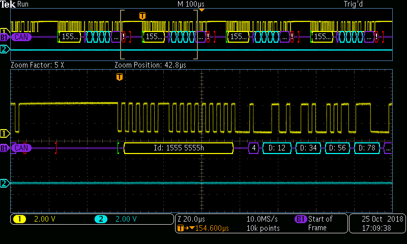
Monitor by CAN analysis meter. It can receive data now, but no data send out. CAN_ES TxOk is always 0.
Where should I pay attention? Thanks.
Hi Harshmeet,
Run the 1st project, it has no data sent out when disable test mode.
For the 3rd project, don't disable test mode, we test it by monitor the data from CAN A to B on CAN analyzer.
Here is code, thanks for your help.
Daniel,
By default, the Driverlib example uses the following GPIO options for CANTX and CANRX (this is defined in device.h file in C:\ti\c2000\C2000Ware_1_00_05_00\device_support\f28004x\common\include). Could you please confirm these are the options used in customer hardware?
//
// CAN External Loopback
//
#define DEVICE_GPIO_CFG_CANRXA GPIO_30_CANRXA // "pinConfig" for CANA RX
#define DEVICE_GPIO_CFG_CANTXA GPIO_31_CANTXA // "pinConfig" for CANA TX
#define DEVICE_GPIO_CFG_CANRXB GPIO_10_CANRXB // "pinConfig" for CANB RX
#define DEVICE_GPIO_CFG_CANTXB GPIO_8_CANTXB // "pinConfig" for CANB TX
I ran can_ex3_external_transmit on my test board and I see the data coming out of CANA_TX pin. Code also works correctly, meaning CAN-A & CAN-B were able to talk to each other. The only change I had to make was to the device .h file, to change the CAN pins. In my board, CAN pin assignments are as follows:
CANTXA |
GPIO4 |
CANRXA |
GPIO5 |
|
|
CANTXB |
GPIO16 |
CANRXB |
GPIO17 |
For some reason, I was unable to capture the traffic on the bus analyzer. I will debug it tomorrow. Scope capture below:
Hi Hareesh,
Thanks for your time do the test and capture waveform.
Which board do you test on? Maybe we can do exactly the same test as you.
Daniel,
It appears there is a small error in the CANBTR value. Can you please try the procedure below and let me know if it helps?
The driverlib generates a value of 000058CB for the CANBTR register. Could you please change this to 00007FC7 and let me know if you are able to see the traffic in CAN bus analyzer. Note that CANBTR register is a protected register and you cannot change the value whenever you like.
Load the code and set a BP at line 195 of can.c file in the project directory. When code hits this line, CANBTR == 000058CB. Now, manually change the register value to 00007FC7. Resume code execution and see if bus traffic is received externally.
Daniel,
To clarify, the issue is that a bit-time of 16 does not yield a bit rate of 50 kbps (it yields 52.08 kbps). You could use a BT of 20 or 25, which yield 50 kbps. All you need to do is to change the BT parameter in the function to 20 or 25.
CAN_setBitRate(CANA_BASE, DEVICE_SYSCLK_FREQ, 500000, 25);
The value I used in the previous post (7FC7) corresponds to BT =25. There is no need to set a BP and manually tweak the CANBTR register value. You could simply change the BT value in the function call above and recompile the project and it should work. I just tested it and it worked.