This thread has been locked.

If you have a related question, please click the "Ask a related question" button in the top right corner. The newly created question will be automatically linked to this question.

CCS/TMS320F28020: Self Designed PCB, Error -1137 @ 0x6) Device is held in reset.

Part Number: TMS320F28020
Other Parts Discussed in Thread: C2000WARE

Tool/software: Code Composer Studio

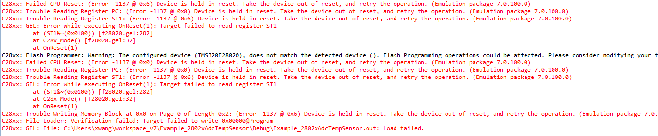
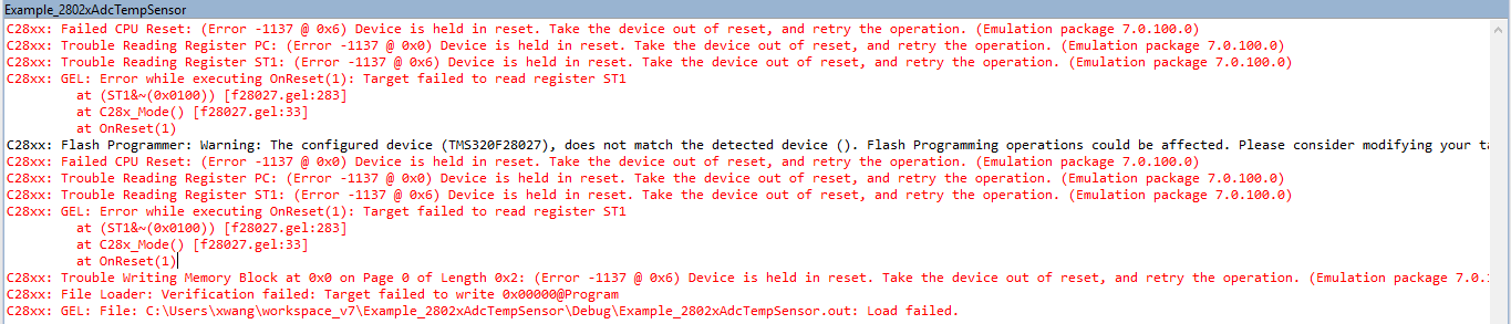
Hi,  I am getting an error when I try to start a debug session. I am using XDS100V2 emulator. I want to download an example provided by C2000ware to the board and I get this error.

error info here:

Here is my schematic file

  • Xiaoming,

    Please take a look at this appnote written to help debug these types of issues  http://www.ti.com/lit/spracf0 

    From the error log I suspect you have a project active and are clicking the "debug" button.  Since there is no JTAG communications the CCS IDE will continue to generate errors for each even(connect, load, run, etc).

    Also, the ccxml is looking for a F28027, but you are using a F28020 device, so that will need to changed as well.

    Let me know how far in terms of steps you are able to get in the document referenced above.

    Best,

    Matthew

  • I have closed other projects and configured the ccxml file to target f28020. The error looks the same.

  • I have found the problem. In schematic file, I connect VDDs to 3.3V which are supposed to connect to 1.8V. Here I want to use internal voltage regulator to provide power to VDDs, so I pull VREGENZ to GND. Now I need to connect VDDs to GND through 1.2uF caps. Is that correct?
  • Xiaoming,
    Yes, that is correct, each VDD pin should have a 1.2uF cap to ground close to the pin. Sorry for not seeing this in the schematic you attached earlier.

    Since you applied 3.3V to the 1.8V voltage rail, there may be some damage to the device.  You can try and re-use it for now, but I would re-commend replacing the device, especially if you see any abnormal behaivor moving forward.


    Best,
    Matthew

  • Thank you for your answer!


    I have one more question. If I want to boot from flash(I don't want my program lost after power off), what is the correct circuit connection for GPIO34, GPIO37 and *TRST?

  • Xiaoming,

    Please see the following section of the F2802x datasheet:

    http://www.ti.com/document-viewer/TMS320F28027/datasheet/boot-rom-litsprs230-0453#litSPRS230-0453  

    You'll want to use mode 3, GETMODE.  There are addresses in the OTP that this mode looks to determine the boot mode, but I beleive with the factory defaults it will go to flash.  The above section or TRM chapter will have more info.

    MODEGPIO37/TDOGPIO34/COMP2OUTTRSTMODE
    3 1 1 0 GetMode
    2 1 0 0 Wait (see Section 6.1.9 for description)
    1 0 1 0 SCI
    0 0 0 0 Parallel IO
    EMU x x 1 Emulation Boot

    Best,

    Matthew

  • Matthew Pate,
    Thank you so much!