This thread has been locked.

If you have a related question, please click the "Ask a related question" button in the top right corner. The newly created question will be automatically linked to this question.

CCS/TMS320F28069: FTDI mini module with TMS320f28069

Part Number: TMS320F28069

Tool/software: Code Composer Studio

Hi,

I am trying to make my custom PCB .

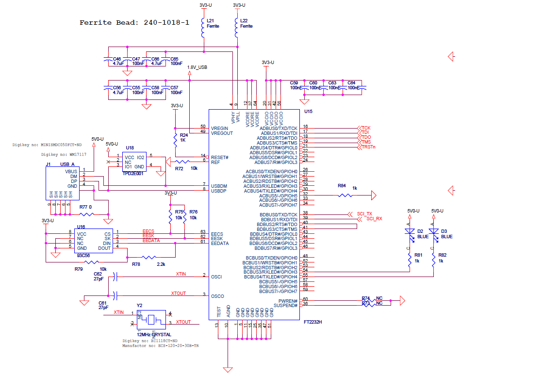
I am using FTDI mini module - https://www.digikey.com/product-detail/en/ftdi/FT2232H%2520MINI%2520MODULE/768-1030-ND/2027252&?gclid=EAIaIQobChMI-pPJ9fv84AIVDVYNCh1Wxgh0EAkYCiABEgKtu_D_BwE

  • OK, so what is your question?
  •  Oh sorry it didn't posted and I didn't noticed.

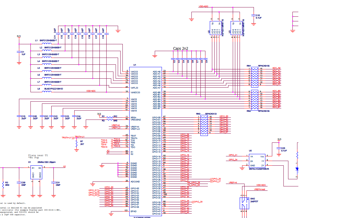
    I am trying to customize DRV8301-F28069 kit. I have connected F28069 and USB mini module as shown in schematic of control card .

    I have connected TDS, TDO , TDI, TRSTn and TMS ( AD0-AD4) pins of USB mini module with TDS, TDO, TDI , TRSTn and TMS of F28069 . 

    I have also connected SCI_TX and SCI_RX pin with GPIO_28 and GPIO_29 as indicated in schematic of F28069 control card.

    I powered up F28069 with 3.3v and I am trying to connect USB module to my PC and CodeComposerStudio but doing that my codecomposerstudio gives error as 

    Error connecting to the target:
    (Error -151 @ 0x0)
    One of the FTDI driver functions used during the connect
    returned bad status or an error. The cause may be one or
    more of: no XDS100 is plugged in, invalid XDS100 serial number,
    blank XDS100 EEPROM, missing FTDI drivers, faulty USB cable.
    Use the xds100serial command-line utility in the 'common/uscif'
    folder to verify the XDS100 can be located.
    (Emulation package 7.0.100.0).

    Note : I have programmed eeprom of USB mini module with help of MPROG to get XDS100v1 drivers and plugging USB to PC shows XDS100 USB port , so I think it works fine.

    Can you help me if I am missing some connection or step. Why ccs cant connect with USB and F2806 ?


  • Ayushi,
    If you open the target configurations window of CCS, and double click the ccxml you made for this target it will bring up a dialog box for set up. If you click the "test" button, can you report back what that output shows for the scan test?

    Matt
  • [Start: Texas Instruments XDS100v2 USB Emulator_0]

    Execute the command:

    %ccs_base%/common/uscif/dbgjtag -f %boarddatafile% -rv -o -F inform,logfile=yes -S pathlength -S integrity

    [Result]


    -----[Print the board config pathname(s)]------------------------------------

    C:\Users\AYUSHI~1\AppData\Local\TEXASI~1\
    CCS\ccsv7\0\0\BrdDat\testBoard.dat

    -----[Print the reset-command software log-file]-----------------------------

    This utility has selected a 100- or 510-class product.
    This utility will load the adapter 'jioserdesusb.dll'.
    The library build date was 'Nov 6 2017'.
    The library build time was '10:36:36'.
    The library package version is '7.0.100.0'.
    The library component version is '35.35.0.0'.
    The controller does not use a programmable FPGA.
    The controller has a version number of '4' (0x00000004).
    The controller has an insertion length of '0' (0x00000000).
    This utility will attempt to reset the controller.
    This utility has successfully reset the controller.

    -----[Print the reset-command hardware log-file]-----------------------------

    The scan-path will be reset by toggling the JTAG TRST signal.
    The controller is the FTDI FT2232 with USB interface.
    The link from controller to target is direct (without cable).
    The software is configured for FTDI FT2232 features.
    The controller cannot monitor the value on the EMU[0] pin.
    The controller cannot monitor the value on the EMU[1] pin.
    The controller cannot control the timing on output pins.
    The controller cannot control the timing on input pins.
    The scan-path link-delay has been set to exactly '0' (0x0000).

    -----[The log-file for the JTAG TCLK output generated from the PLL]----------

    There is no hardware for programming the JTAG TCLK frequency.

    -----[Measure the source and frequency of the final JTAG TCLKR input]--------

    There is no hardware for measuring the JTAG TCLK frequency.

    -----[Perform the standard path-length test on the JTAG IR and DR]-----------

    This path-length test uses blocks of 64 32-bit words.

    The test for the JTAG IR instruction path-length failed.
    The JTAG IR instruction scan-path is stuck-at-ones.

    The test for the JTAG DR bypass path-length failed.
    The JTAG DR bypass scan-path is stuck-at-ones.

    -----[Perform the Integrity scan-test on the JTAG IR]------------------------

    This test will use blocks of 64 32-bit words.
    This test will be applied just once.

    Do a test using 0xFFFFFFFF.
    Scan tests: 1, skipped: 0, failed: 0
    Do a test using 0x00000000.
    Test 2 Word 0: scanned out 0x00000000 and scanned in 0xFFFFFFFF.
    Test 2 Word 1: scanned out 0x00000000 and scanned in 0xFFFFFFFF.
    Test 2 Word 2: scanned out 0x00000000 and scanned in 0xFFFFFFFF.
    Test 2 Word 3: scanned out 0x00000000 and scanned in 0xFFFFFFFF.
    Test 2 Word 4: scanned out 0x00000000 and scanned in 0xFFFFFFFF.
    Test 2 Word 5: scanned out 0x00000000 and scanned in 0xFFFFFFFF.
    Test 2 Word 6: scanned out 0x00000000 and scanned in 0xFFFFFFFF.
    Test 2 Word 7: scanned out 0x00000000 and scanned in 0xFFFFFFFF.
    The details of the first 8 errors have been provided.
    The utility will now report only the count of failed tests.
    Scan tests: 2, skipped: 0, failed: 1
    Do a test using 0xFE03E0E2.
    Scan tests: 3, skipped: 0, failed: 2
    Do a test using 0x01FC1F1D.
    Scan tests: 4, skipped: 0, failed: 3
    Do a test using 0x5533CCAA.
    Scan tests: 5, skipped: 0, failed: 4
    Do a test using 0xAACC3355.
    Scan tests: 6, skipped: 0, failed: 5
    Some of the values were corrupted - 83.3 percent.

    The JTAG IR Integrity scan-test has failed.

    -----[Perform the Integrity scan-test on the JTAG DR]------------------------

    This test will use blocks of 64 32-bit words.
    This test will be applied just once.

    Do a test using 0xFFFFFFFF.
    Scan tests: 1, skipped: 0, failed: 0
    Do a test using 0x00000000.
    Test 2 Word 0: scanned out 0x00000000 and scanned in 0xFFFFFFFF.
    Test 2 Word 1: scanned out 0x00000000 and scanned in 0xFFFFFFFF.
    Test 2 Word 2: scanned out 0x00000000 and scanned in 0xFFFFFFFF.
    Test 2 Word 3: scanned out 0x00000000 and scanned in 0xFFFFFFFF.
    Test 2 Word 4: scanned out 0x00000000 and scanned in 0xFFFFFFFF.
    Test 2 Word 5: scanned out 0x00000000 and scanned in 0xFFFFFFFF.
    Test 2 Word 6: scanned out 0x00000000 and scanned in 0xFFFFFFFF.
    Test 2 Word 7: scanned out 0x00000000 and scanned in 0xFFFFFFFF.
    The details of the first 8 errors have been provided.
    The utility will now report only the count of failed tests.
    Scan tests: 2, skipped: 0, failed: 1
    Do a test using 0xFE03E0E2.
    Scan tests: 3, skipped: 0, failed: 2
    Do a test using 0x01FC1F1D.
    Scan tests: 4, skipped: 0, failed: 3
    Do a test using 0x5533CCAA.
    Scan tests: 5, skipped: 0, failed: 4
    Do a test using 0xAACC3355.
    Scan tests: 6, skipped: 0, failed: 5
    Some of the values were corrupted - 83.3 percent.

    The JTAG DR Integrity scan-test has failed.

  • Do I need to plug separate xds100 debug emulator externally?
  • Ayushi,
    Thanks for reporting back the test I had you perform is a simpler set of actions for the debugger. I notice that in the output the ccxml is attempting to connect to a XDS100v2; but I beleive in your orginal post you mentioned that the FTDI device was programmed as a XDS100v1.

    You should be able to change the ccxml target to the XDS100v1, and then re-do the "Test" button.

    Best,
    Matthew
  • Ayushi,

    Wanted to see if the above had resolved your issue, or there is still more debug needed?

    Best,

    Matthew