- Ask a related questionWhat is a related question?A related question is a question created from another question. When the related question is created, it will be automatically linked to the original question.
Hello,
I am using Proteus 8.8 to build a schematic for tms320f28027pt but when i load the program file "HEX" to proteus the simulation runs but the gpios (epwm1) stay high impedance..
This is the code i am using (just to run a pwm)
#include "DSP28x_Project.h"     // Device Headerfile and Examples Include File


// Prototype statements for functions found within this file.
void InitEPwm1Example(void);


// Global variables used in this example

// Configure the period for each timer
#define EPWM1_TIMER_TBPRD  30000                 //1Hz
#define EPWM1_CMPA     EPWM1_TIMER_TBPRD/2       // 20% duty cycle


void main(void)
{
// WARNING: Always ensure you call memcpy before running any functions from RAM
// InitSysCtrl includes a call to a RAM based function and without a call to
// memcpy first, the processor will go "into the weeds"
   #ifdef _FLASH
    memcpy(&RamfuncsRunStart, &RamfuncsLoadStart, (size_t)&RamfuncsLoadSize);
   #endif

// Step 1. Initialize System Control:
// PLL, WatchDog, enable Peripheral Clocks
// This example function is found in the f2802x_SysCtrl.c file.
   InitSysCtrl();


// Step 2. Initialize GPIO:
// This example function is found in the f2802x_Gpio.c file and
// illustrates how to set the GPIO to it's default state.
// InitGpio();  // Skipped for this example

// For this case just init GPIO pins for ePWM1, ePWM2, ePWM3
// These functions are in the f2802x_EPwm.c file
   InitEPwm1Gpio();

  //SysCtrlRegs.CLKCTL.bit.XTALOSCOFF=0;
// Step 4. Initialize all the Device Peripherals:
// Not required for this example

// For this example, only initialize the ePWM

   EALLOW;
   SysCtrlRegs.PCLKCR0.bit.TBCLKSYNC = 0;
   EDIS;

   InitEPwm1Example();


   EALLOW;
   SysCtrlRegs.PCLKCR0.bit.TBCLKSYNC = 1;
   EDIS;


// Step 6. IDLE loop. Just sit and loop forever (optional):


       for (;;){

       }
}


void InitEPwm1Example()
{
   // Setup TBCLK
   EPwm1Regs.TBCTL.bit.CTRMODE = TB_COUNT_UP; // Count up
   EPwm1Regs.TBPRD = EPWM1_TIMER_TBPRD;       // Set timer period
   EPwm1Regs.TBCTL.bit.PHSEN = TB_DISABLE;    // Disable phase loading
   EPwm1Regs.TBPHS.half.TBPHS = 0x0000;       // Phase is 0
   EPwm1Regs.TBCTR = 0x0000;                  // Clear counter
   EPwm1Regs.TBCTL.bit.HSPCLKDIV = 1;   // Clock ratio to SYSCLKOUT
   EPwm1Regs.TBCTL.bit.CLKDIV = 0;

   // Setup shadow register load on ZERO
   EPwm1Regs.CMPCTL.bit.SHDWAMODE = CC_SHADOW;
   EPwm1Regs.CMPCTL.bit.SHDWBMODE = CC_SHADOW;
   EPwm1Regs.CMPCTL.bit.LOADAMODE = CC_CTR_ZERO;
   EPwm1Regs.CMPCTL.bit.LOADBMODE = CC_CTR_ZERO;

   // Set Compare values
   EPwm1Regs.CMPA.half.CMPA = EPWM1_CMPA;    // Set compare A value

   // Set actions
   EPwm1Regs.AQCTLA.bit.ZRO = AQ_SET;            // Set PWM1A on Zero
   EPwm1Regs.AQCTLA.bit.CAU = AQ_CLEAR;          // Clear PWM1A on event A, up count


}


// No more.
//===========================================================================
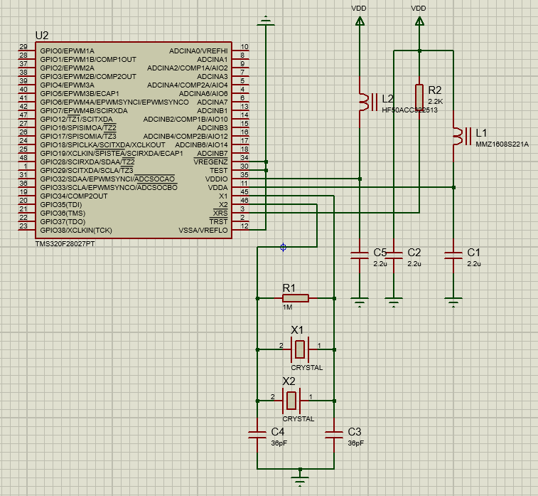
This is the schematics:
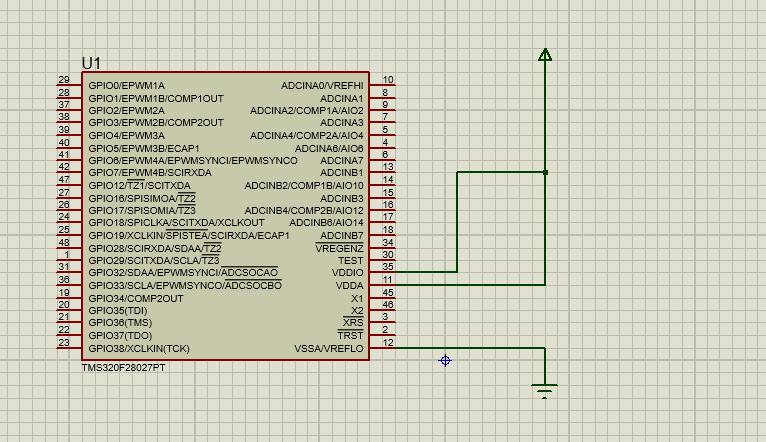
SO is there something wrong with Hex file!? or just a compatibility issue with proteus?
Thanks,