This thread has been locked.
If you have a related question, please click the "Ask a related question" button in the top right corner. The newly created question will be automatically linked to this question.
Hi expert,
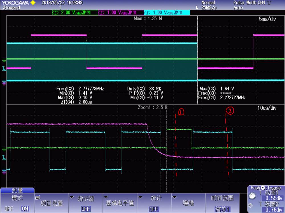
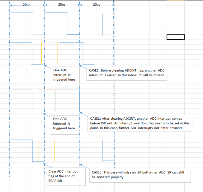
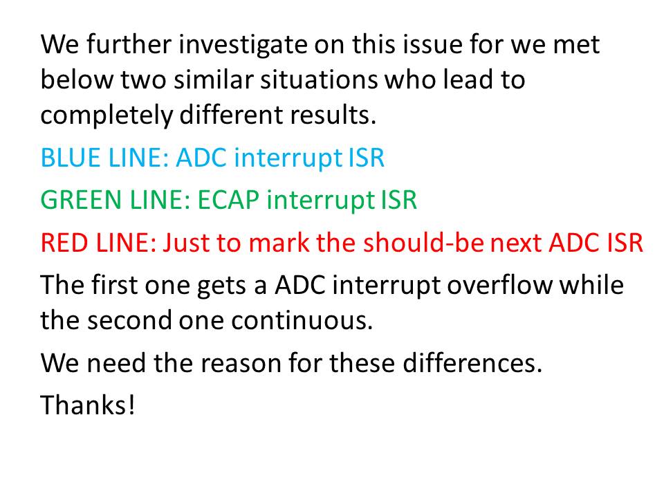
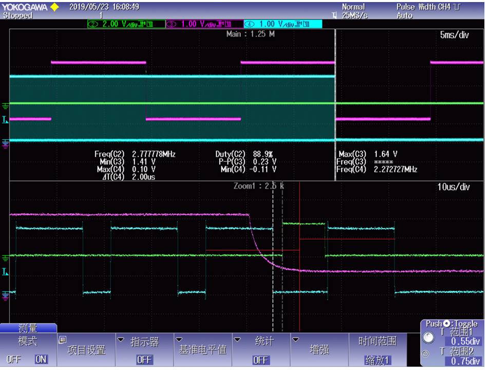
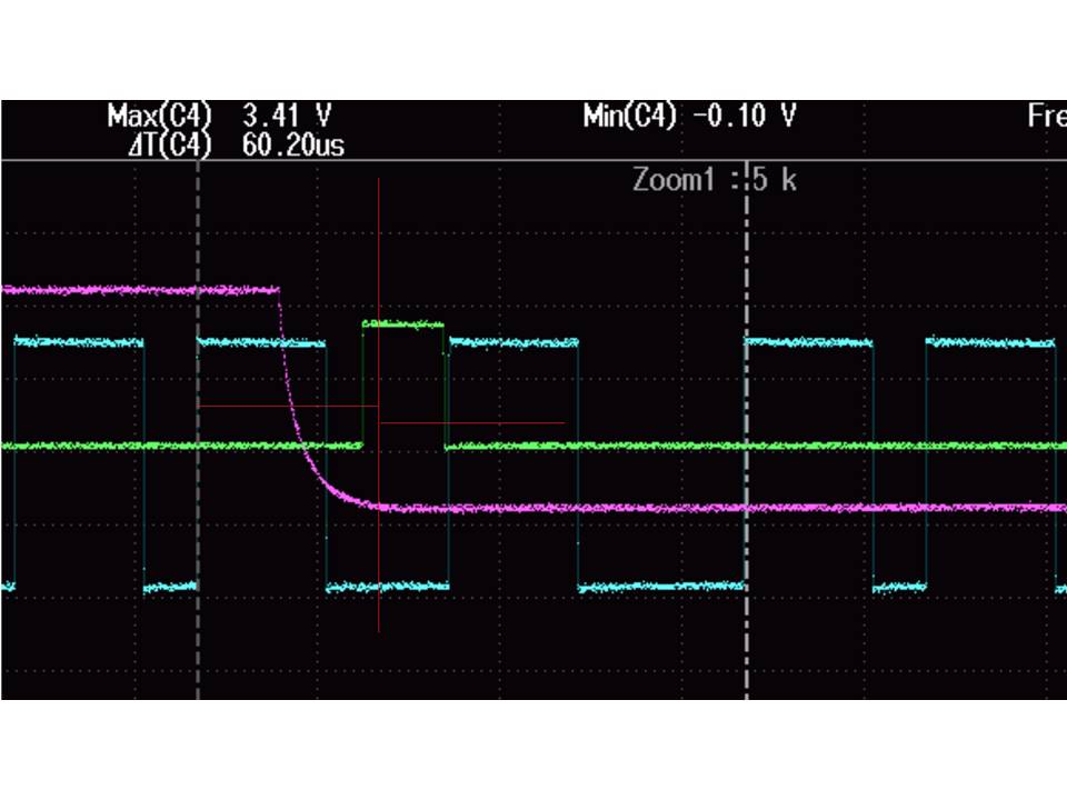
My customer implementing both ECAP and ADC interrupt and both of their ISR are quite long with no nesting and preempting. The encountered problem when running for sometime, both ADC and ECAP IFR are not set and ADCINTOVF corresponding bits are set (set attached file).
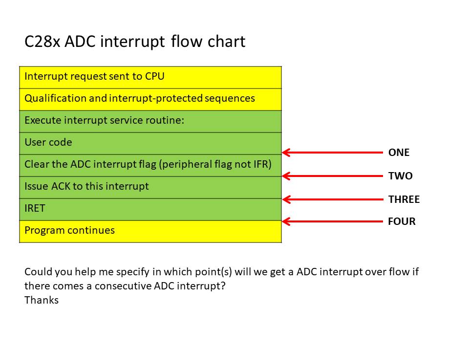
I find there are little explanation for ADC interrupt overflow circumstance. Could you help me with more details of possibilities/examples in which this issue will occur?
Thanks
Sheldon
Hi Sheldon,
In the ADC ISR routines, can you check if the interrupts are cleared after being serviced? Seems like the interrupts are not cleared, causing overflow flags to be set, as reflected in ADCOVF.
Regards,
Joseph
Hi Joseph,
I will provide more details and need more help on this issue for my customer have to explain to their end customer.
In simple words, they are running two ISR without nesting, the ECAP ISR and the ADC ISR. they indicates the timing of these two ISR by toggling GPIOs. high voltage level indicates the ISR is funning.
In lower part of below graph, green line indicates ECAP ISR and blue line indicates ADC ISR. You can see that the ADC ISR should start at "one" but delayed and the next ADC ISR should start at "two". In the circumstance, the delayed ADC ISR is still running, will this cause an interrupt overflow? For ADC ISR is not triggered any more.
In another situation.
This case also gets a delay in ADC ISR but following ADC ISR are triggered normally. Why this situation didn't get an interrupt overflow? Are there anything to do with the running of last ADC ISR and newly raise ADC interrupt?
Sheldon
Thanks
Hi Sheldon,
Thanks for sending the sequence of events through the GPIO toggle but unfortunately, I cannot make any generalizations from it without looking at the ISR, setup, and conversion codes. If it is possible to share a snippet of these please do so as it may help us understand why code is producing interrupt overflows.
Regards,
Joseph
Hi Joseph,
Below is ADC setup code:
void Adc_Init(void) { // Interrupts that are used in this example are re-mapped to ISR functions // found within this file. Interrupt_register(INT_ADCA1, &adcA1ISR); // Setup VREF as external 3V ADC_setVREF(ADCA_BASE, ADC_REFERENCE_EXTERNAL, ADC_REFERENCE_3_3V); ADC_setVREF(ADCB_BASE, ADC_REFERENCE_EXTERNAL, ADC_REFERENCE_3_3V); ADC_setVREF(ADCC_BASE, ADC_REFERENCE_EXTERNAL, ADC_REFERENCE_3_3V); // ADC_setVREF(ADCA_BASE, ADC_REFERENCE_INTERNAL, ADC_REFERENCE_3_3V); // ADC_setVREF(ADCB_BASE, ADC_REFERENCE_INTERNAL, ADC_REFERENCE_3_3V); // ADC_setVREF(ADCC_BASE, ADC_REFERENCE_INTERNAL, ADC_REFERENCE_3_3V); // Set ADCCLK divider to /4 ADC_setPrescaler(ADCA_BASE, ADC_CLK_DIV_4_0); ADC_setPrescaler(ADCB_BASE, ADC_CLK_DIV_4_0); ADC_setPrescaler(ADCC_BASE, ADC_CLK_DIV_4_0); // Set pulse positions to late ADC_setInterruptPulseMode(ADCA_BASE, ADC_PULSE_END_OF_CONV); ADC_setInterruptPulseMode(ADCB_BASE, ADC_PULSE_END_OF_CONV); ADC_setInterruptPulseMode(ADCC_BASE, ADC_PULSE_END_OF_CONV); // Power up the ADC and then delay for 1 ms ADC_enableConverter(ADCA_BASE); ADC_enableConverter(ADCB_BASE); ADC_enableConverter(ADCC_BASE); DEVICE_DELAY_US(1000); // Configure the SOC to occur on the first up-count event EPWM_setADCTriggerSource(EPWM7_BASE, EPWM_SOC_A, EPWM_SOC_TBCTR_ZERO); // EPWM_setADCTriggerSource(EPWM2_BASE, EPWM_SOC_A, EPWM_SOC_TBCTR_ZERO); EPWM_setADCTriggerSource(EPWM2_BASE, EPWM_SOC_A, EPWM_SOC_TBCTR_PERIOD); // EPWM_setADCTriggerSource(EPWM7_BASE, EPWM_SOC_A, EPWM_SOC_TBCTR_U_CMPA); // EPWM_setADCTriggerSource(EPWM2_BASE, EPWM_SOC_A, EPWM_SOC_TBCTR_U_CMPA); EPWM_setADCTriggerEventPrescale(EPWM7_BASE, EPWM_SOC_A, 1); EPWM_setADCTriggerEventPrescale(EPWM2_BASE, EPWM_SOC_A, 1); // Configure SOC0 of ADCA/ADCC to convert pin XX with a sample window of 10 // SYSCLK cycles. The EPWM7SOCA signal will be the trigger. ADC_setupSOC(ADCA_BASE, ADC_SOC_NUMBER0, ADC_TRIGGER_EPWM7_SOCA, ADC_CH_ADCIN10, 10); ADC_setupSOC(ADCA_BASE, ADC_SOC_NUMBER1, ADC_TRIGGER_EPWM7_SOCA, ADC_CH_ADCIN2, 10); ADC_setupSOC(ADCA_BASE, ADC_SOC_NUMBER2, ADC_TRIGGER_EPWM7_SOCA, ADC_CH_ADCIN0, 10); ADC_setupSOC(ADCA_BASE, ADC_SOC_NUMBER3, ADC_TRIGGER_EPWM7_SOCA, ADC_CH_ADCIN6, 10); ADC_setupSOC(ADCC_BASE, ADC_SOC_NUMBER0, ADC_TRIGGER_EPWM7_SOCA, ADC_CH_ADCIN0, 10); ADC_setupSOC(ADCC_BASE, ADC_SOC_NUMBER1, ADC_TRIGGER_EPWM7_SOCA, ADC_CH_ADCIN4, 10); ADC_setupSOC(ADCC_BASE, ADC_SOC_NUMBER2, ADC_TRIGGER_EPWM7_SOCA, ADC_CH_ADCIN2, 10); ADC_setupSOC(ADCC_BASE, ADC_SOC_NUMBER3, ADC_TRIGGER_EPWM7_SOCA, ADC_CH_ADCIN1, 10); ADC_setupSOC(ADCB_BASE, ADC_SOC_NUMBER0, ADC_TRIGGER_EPWM2_SOCA, ADC_CH_ADCIN8, 10); ADC_setupSOC(ADCB_BASE, ADC_SOC_NUMBER1, ADC_TRIGGER_EPWM2_SOCA, ADC_CH_ADCIN4, 10); ADC_setupSOC(ADCB_BASE, ADC_SOC_NUMBER2, ADC_TRIGGER_EPWM2_SOCA, ADC_CH_ADCIN3, 10); ADC_setupSOC(ADCB_BASE, ADC_SOC_NUMBER3, ADC_TRIGGER_EPWM2_SOCA, ADC_CH_ADCIN2, 10); // Start ePWMx, enabling SOCA EPWM_enableADCTrigger(EPWM7_BASE, EPWM_SOC_A); EPWM_enableADCTrigger(EPWM2_BASE, EPWM_SOC_A); // Set SOC0 to set the interrupt 1 flag. Enable the interrupt and make // sure its flag is cleared. // ADC_setInterruptSource(ADCA_BASE, ADC_INT_NUMBER1, ADC_SOC_NUMBER2); ADC_enableInterrupt(ADCA_BASE, ADC_INT_NUMBER1); ADC_clearInterruptStatus(ADCA_BASE, ADC_INT_NUMBER1); // Enable ADC interrupt Interrupt_enable(INT_ADCA1); }
Below is ECAP setup code:
void Init_Capture(void) { EALLOW; InputXbarRegs.INPUT15SELECT = 13; // Set eCAP1 source to GPIO-pin ECap1Regs.ECCTL0.bit.INPUTSEL = 14; EDIS; Interrupt_register(INT_ECAP1, &Capture_Process); EALLOW; /****************** eCap1 config ************************/ ECap1Regs.ECEINT.all = 0x0000; /* Disable all capture interrupts */ ECap1Regs.ECCLR.all = 0xFFFF; /* Clear all CAP interrupt flags */ ECap1Regs.ECCTL1.bit.CAPLDEN = 0; /* Disable CAP1-CAP4 register loads */ ECap1Regs.ECCTL2.bit.TSCTRSTOP = 0; /* Make sure the counter is stopped */ ECap1Regs.ECCTL2.bit.CONT_ONESHT = 0; /* continuous mode */ ECap1Regs.ECCTL2.bit.STOP_WRAP = 0; /* Wrap after Capture Event 1 */ ECap1Regs.ECCTL1.bit.CAP1POL = 1; /* Falling edge */ ECap1Regs.ECCTL1.bit.CAP2POL = 0; /* Rising edge */ ECap1Regs.ECCTL1.bit.CAP3POL = 1; /* Falling edge */ ECap1Regs.ECCTL1.bit.CAP4POL = 0; /* Rising edge */ ECap1Regs.ECCTL1.bit.CTRRST1 = 1; /* Difference operation */ ECap1Regs.ECCTL1.bit.CTRRST2 = 1; /* Difference operation */ ECap1Regs.ECCTL1.bit.CTRRST3 = 1; /* Difference operation */ ECap1Regs.ECCTL1.bit.CTRRST4 = 1; /* Difference operation */ ECap1Regs.ECCTL2.bit.SYNCI_EN = 1; /* Enable sync in */ ECap1Regs.ECCTL2.bit.SYNCO_SEL = 0; /* Pass through */ ECap1Regs.ECCTL1.bit.CAPLDEN = 1; /* Enable capture units */ ECap1Regs.ECCTL2.bit.TSCTRSTOP = 1; /* Start Counter */ ECap1Regs.ECEINT.bit.CEVT1 = 1; /* 1 events = __interrupt */ EDIS; SysCtl_enablePeripheral(SYSCTL_PERIPH_CLK_ECAP1); //ECAP_enableInterrupt(); Interrupt_enable(INT_ECAP1); }
Below are the two ISRs:
Thanks
Sheldon
Hi Joseph,
Customer removed any use code in the ISR so it seems straight forward :)
I still have some questions on details regarding your comment: ADC interrupt overflow will occur whenever another ADC interrupt occurs while there is an active ADC interrupt that is not yet cleared.
We have two situation who both have another ADC interrupt occurs when there is still ADC ISR running. Please check my attached PPT for details on this!
Thanks!
Sheldon