This thread has been locked.
If you have a related question, please click the "Ask a related question" button in the top right corner. The newly created question will be automatically linked to this question.
I want to implement an I2C signal buffer to drive my I2C LCD.
The reason is that without the buffer, the DSP 28020 GPIO is not powerful to drive it.
You can see the waveform below. Rise time is not decent.
Code is successfully generated. 0x7C(slave address), 0x80, 0x28 are sent with a stop on the DATA wire.
After I add the I2C signal buffer chip, LCD is not properly initialized.
Because the waveform now looks like this
DSP is only able to send the first byte, 0x7C, the rest 2 bytes are missing and no stop condition is generated.
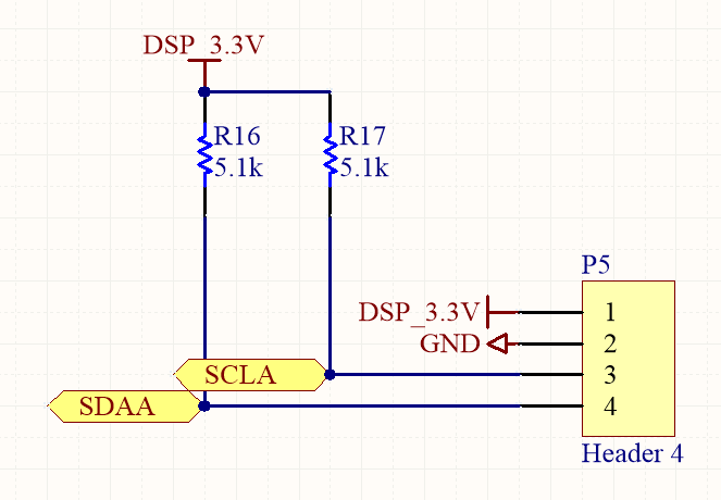
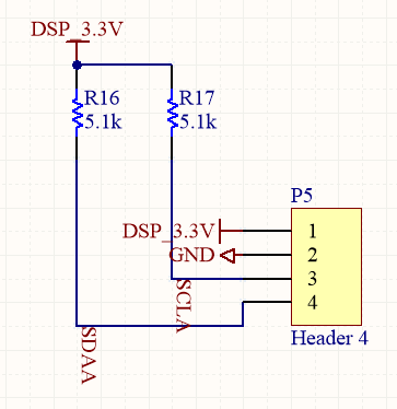
The buffer chip I use is TCA9803 from TI, and the circuit schematic is here.
I use 3.3V here. EN is directly connected to 3.3V.
I guess it is a hardware problem. Can anyone help me with this?
Thank you for your reply!
For the first graph, I connect LCD directly to GPIOs without pull up resistor. Is it the correct configuration or do I need to add pull up resistors like this?
For the second graph, I probe on buffer to slave. My guessing is that the response from slave is not able to transmit back to DSP(master).
Regards,
Xiaoming
Hi Xiaoming,
Xiaoming Wang said:For the first graph, I connect LCD directly to GPIOs without pull up resistor. Is it the correct configuration or do I need to add pull up resistors like this?
You may have been using the F28020's internal pull-up resistors. You should try disabling the internal pull-ups (using GPAPUD or GPBPUD registers) and use external pull-up resistors, like the schematic you showed. You can look at the waveforms and adjust the resistance as needed (5.1K may be OK).
Xiaoming Wang said:For the second graph, I probe on buffer to slave. My guessing is that the response from slave is not able to transmit back to DSP(master).
That's what it looked like to me initially. Though it does seem odd that the 9th clock pulse from the master (for ACK/NACK) is not seen. Maybe the slave is holding SDA low to signal an ACK and waiting for the clock pulse from the master, but it never sees it. The SDA signal is very noisy, so I'm not fully sure.
Could you probe the master/buffer interface and provide a screenshot here? Also checking the I2C registers on the master side after this failed communication may say something (I2CSTR and I2CMDR registers at least).
Best,
Kevin
Hi Kevin,
Thank you for your reply!
I find the hardware reason of rise time issue. Now I remove the capacitors on the I2C bus wire and now the rise time looks good.
I also tried disable internal pull up and added 2 3.6kohm external pull up resistors(I did not find a 5.1kohm). The rise time is even better.
For the I2C buffer chip, it is not easy to reach master/buffer interface so I am not able to provide you a screenshot.
I checked the I2C registers realtime values on CCS. I2CSTR jumps between 0x1421 and 0x0421. I2CMDR is 0x4220.
What do these indicate?
One more question, I use I2C function in a very bad EMI Environment. There is a ~30kHz resonant converter close to the I2C port and the DSP. I want to use LCD to display converter's operation status but it goes no responding easily (few seconds after the converter starts) so I guess the I2C signal is interfered. Do you know any way to counteract EMI or refresh/reconnect the I2C device?
Regards,
Xiaoming
Hi Xiaoming,
That's good that you found some hardware improvements for the signals.
Regarding the register values you should check what these bits mean in the I2C section of the TRM (Technical Reference Manual) here, specifically the I2C_REGS section:
Xiaoming Wang said:I2CSTR jumps between 0x1421 and 0x0421
This change is just the 'Bus Busy' bit (BB) getting set when there's communication on the bus and the 'Slave Direction' bit (SDIR) when the devices is addressed as a slave.
Xiaoming Wang said:One more question, I use I2C function in a very bad EMI Environment. There is a ~30kHz resonant converter close to the I2C port and the DSP. I want to use LCD to display converter's operation status but it goes no responding easily (few seconds after the converter starts) so I guess the I2C signal is interfered. Do you know any way to counteract EMI or refresh/reconnect the I2C device?
Ideally you'd like to route communication signals in a way that would reduce EMI. You can search for general information online on best practices hardware wise, such as adding filtering, decoupling supplies, etc. Software wise, I think beneficial techniques used would depend on your application and the device you're communicating with. Not sure if you could utilize communication redundancy, or something like that, with your LCD device.
Best,
Kevin
Thank you, Kevin.
I will add decoupling and low pass filter in next version.
I still want to learn about software solution because hardware solution is not a guarantee.
In section 'External Slave Device Hanging the Bus by Holding SDA Low', I see this:
'In this scenario the external slave might be holding SDA low to transmit a 0 (or ACK).'
How do I detect SDA holding low by coding?
Thank you!
Regards,
Xiaoming
Hi Xiaoming,
Checking for an Arbitration Lost condition after re-initiating a transfer may be an option, like is discussed on the wiki page, but this seems like it may have varying results:
"Even in this case it's not until it tries to transmit a '1' that it will actually release SDA after seeing SCL fall. The end result is that the bus will hang. If the I2C tries to initiate a new transfer it will hit an "arbitration lost" condition because SDA won't match the address it's sending."
You may also try switching the I2C pins to GPIOs and check the state of the pins, then toggle as needed to release the bus.
Best,
Kevin
Hi Xiaoming,
Haven't heard from you in a little over a week. Were you able to resolve your issue?
If so, I'm going to go ahead and close this post. If you still need additional support feel free to post here, or if this post closes due to timeout, you can post a new question on the forum.
Best,
Kevin
Hi Kevin,
Thank you for your help! I was busy these days and did not reply. I have designed a low pass filter for I2C port. I will try software side solution if necessary.
Now I am working on I2C on 28335 platform. Looks like 28335 GPIO for I2C is different from that of 28020. I have problem configure the pins. I don't see SCL and SDA signal at output. They are all-time high and the voltage is higher than 3.3V, it is around 3.7V. Is there something wrong with the hardware?
I will also attach my I2C codes.
void I2CA_Init(void); Uint16 I2CA_WriteData(Uint16 slave_add, Uint16 add, Uint16 data); void init_LCD(); #define I2C_LCD 0x3E #define I2C_RGB 0x60 #define I2C_NUMBYTES 2 void InitI2CGpio() { EALLOW; // // Enable internal pull-up for the selected pins // Pull-ups can be enabled or disabled disabled by the user. // This will enable the pullups for the specified pins. // Comment out other unwanted lines. // GpioCtrlRegs.GPBPUD.bit.GPIO32 = 0; // Enable pull-up for GPIO32 (SDAA) GpioCtrlRegs.GPBPUD.bit.GPIO33 = 0; // Enable pull-up for GPIO33 (SCLA) // // Set qualification for selected pins to asynch only // This will select asynch (no qualification) for the selected pins. // Comment out other unwanted lines. // GpioCtrlRegs.GPBQSEL1.bit.GPIO32 = 3; // Asynch input GPIO32 (SDAA) GpioCtrlRegs.GPBQSEL1.bit.GPIO33 = 3; // Asynch input GPIO33 (SCLA) // // Configure SCI pins using GPIO regs // This specifies which of the possible GPIO pins will be I2C functional // pins. Comment out other unwanted lines. // GpioCtrlRegs.GPBMUX1.bit.GPIO32 = 1; // Configure GPIO32 to SDAA GpioCtrlRegs.GPBMUX1.bit.GPIO33 = 1; // Configure GPIO33 to SCLA EDIS; } void I2CA_Init(void) { // Initialize I2C I2caRegs.I2CSAR = I2C_LCD; // Slave address - EEPROM control code #if (CPU_FRQ_150MHZ) // Default - For 150MHz SYSCLKOUT I2caRegs.I2CPSC.all = 14; // Prescaler - need 7-12 Mhz on module clk (150/15 = 10MHz) #endif #if (CPU_FRQ_100MHZ) // For 100 MHz SYSCLKOUT I2caRegs.I2CPSC.all = 9; // Prescaler - need 7-12 Mhz on module clk (100/10 = 10MHz) #endif I2caRegs.I2CCLKL = 45; // NOTE: must be non zero I2caRegs.I2CCLKH = 45; // NOTE: must be non zero // I2caRegs.I2CIER.all = 0x24; // Enable SCD & ARDY interrupts I2caRegs.I2CMDR.all = 0x0020; // Take I2C out of reset // Stop I2C when suspended I2caRegs.I2CFFTX.all = 0x6000; // Enable FIFO mode and TXFIFO I2caRegs.I2CFFRX.all = 0x2040; // Enable RXFIFO, clear RXFFINT, return; } Uint16 I2CA_WriteData(Uint16 slave_add, Uint16 add, Uint16 data) { // Uint16 i; // Wait until the STP bit is cleared from any previous master communication. // Clearing of this bit by the module is delayed until after the SCD bit is // set. If this bit is not checked prior to initiating a new message, the // I2C could get confused. if (I2caRegs.I2CMDR.bit.STP == 1) { return I2C_STP_NOT_READY_ERROR; } // Setup slave address I2caRegs.I2CSAR = slave_add; // Check if bus busy if (I2caRegs.I2CSTR.bit.BB == 1) { return I2C_BUS_BUSY_ERROR; } // Setup number of bytes to send // MsgBuffer + Address I2caRegs.I2CCNT = 2; // Setup data to send I2caRegs.I2CDXR = add; I2caRegs.I2CDXR = data; // Send start as master transmitter I2caRegs.I2CMDR.all = 0x6E20; return I2C_SUCCESS; } void init_LCD()//70.5ms total { //init 3 times, function set int i; for(i=0;i<3;i++) { Error=I2CA_WriteData(I2C_LCD,0x80,0x28); DELAY_US(15000); } //display control Error=I2CA_WriteData(I2C_LCD,0x80,0x0C); DELAY_US(10000); //clear display Error=I2CA_WriteData(I2C_LCD,0x80,0x01); DELAY_US(12000); //entry mode set Error=I2CA_WriteData(I2C_LCD,0x80,0x06); DELAY_US(500); //set RGB reg mode 1, output, mode2 Error=I2CA_WriteData(I2C_RGB,0x00,0x00); DELAY_US(500); Error=I2CA_WriteData(I2C_RGB,0x08,0xFF); DELAY_US(500); Error=I2CA_WriteData(I2C_RGB,0x01,0x20); DELAY_US(500); //set RGB white Error=I2CA_WriteData(I2C_RGB,0x04,0x80); DELAY_US(500); Error=I2CA_WriteData(I2C_RGB,0x03,0x80); DELAY_US(500); Error=I2CA_WriteData(I2C_RGB,0x02,0x80); DELAY_US(500); }
Regards,
Xiaoming
Hi Xiaoming,
In your code you are enabling the internal pull-ups. Maybe try disabling them instead since you're using external pull-up resistors. Other than that the pin configuration looks OK.
3.7V is a little higher than the recommended "High-level input voltage" from the datasheet (3.465V). May be worthwhile to look into why you're seeing a higher 3.3V supply voltage.
Is the software you're using the same as that of the F2802x platform which you had working, other than some minor configuration changes for the f2833x?
Best,
Kevin
Hi Kevin,
Thank you for your reply!
I have tried disabling pull-up resistor. I don't see I2C signal on SDA and SCL. They are all time high.
As for the 3.7V problem, if I disconnect I2C LCD, voltage on SDA and SCL is 3.3V. After I connect the LCD, they change to 3.7V.
I also checked the hardware connection. SDA and SCL are connected to corresponding DSP pin.
DSP 28335 is used in a different application so the software is different. I2C code is quite similar though.
I will further look into this issue.
Happy holiday.
Xiaoming
Hi Xiaoming,
The F2833x I2C may be having trouble pulling the SDA/SCL lines low at 3.7V. I'd suggest checking the schematic of the LCD screen's I2C lines. Is it being externally powered at 3.7V?
If you disconnect the LCD and run your application code do you see communication on the bus (start condition / slave address)? If so, then something related to the LCD is likely the issue.
Best,
Kevin
Hi Kevin,
Software is not the same. They are for different purposes.
I disconnect the LCD and SCL and SDA are all-time high. I don't see any toggles.
Maybe the pins are damaged?
Regards,
Xiaoming
Hi Xiaoming,
Without the LCD connected and with proper pull-ups, you should be able to see the slave addressing portion followed by a NACK (since there's no slave device on the bus) when you run your software.
Your bus is stuck at 3.3V, not 3.7V now, right? Are you positive you're triggering the bus on your oscilloscope correctly? Not sure if your software is set-up to re-try slave addressing over-and-over, but if it's not it may be difficult to capture the slave addressing portion.
Best,
Kevin
Hi Kevin,
I update my code to test the I2C ports. I use internal pull-up and disconnect LCD. I don't see any output still. I2C ports are stuck at 3.3V.
I watch some variables on CCS:
I2caRegs.I2CSAR
I2caRegs.I2CDXR
I2caRegs.I2CCNT
Error
They are all 0.
I am sure the DSP goes through I2C functions because I have a flag before the return command and the flag is set.
No idea what is happening here. Do you have any idea?
Regards,
Xiaoming
Hi Xiaoming,
Do you set I2CSAR in your program to a slave address? It seems like you need to do some further debugging, utilizing breakpoints to check the register values and bus behavior at different times during execution.
Can you try running the i2c_eeprom example within c2000ware and see anything is on the I2C bus? You may need to change the GPIO configuration depending on what pins you're using for SDA/SCL. Directory location below:
C:\ti\c2000\C2000Ware_2_00_00_02\device_support\f2802x\examples\structs\i2c_eeprom
Best,
KEvin
Hi Kevin,
Thank you for your suggestion! We are working towards success.
Here are my updates:
I tried i2c_eeprom and saw output. I rewrote my code in i2c_eeprom example and successfully lighted up my LCD.
I transplanted this code to my existing project code but it's not working.
I will double check my code, if I can't figure out, I will upload my code and ask for help!
Thank you!
Regards,
Xiaoming
Hi Kevin,
I can not figure out the problem.
I upload two C program files for you to review.
The first can light up LCD, the second can not.
//########################################################################### // // FILE: Example_2833xI2C_eeprom.c // // TITLE: I2C EEPROM Example // //! \addtogroup f2833x_example_list //! <h1>I2C EEPROM (i2c_eeprom)</h1> //! //! This program requires an external I2C EEPROM connected to //! the I2C bus at address 0x50. \n //! This program will write 1-14 words to EEPROM and read them back. //! The data written and the EEPROM address written to are contained //! in the message structure, \b I2cMsgOut1. The data read back will be //! contained in the message structure \b I2cMsgIn1. //! //! \b Watch \b Variables \n //! - I2cMsgIn1 //! - I2cMsgOut1 // //########################################################################### // $TI Release: F2833x Support Library v2.00.00.00 $ // $Release Date: Thu Oct 18 15:47:35 CDT 2018 $ // $Copyright: // Copyright (C) 2009-2018 Texas Instruments Incorporated - http://www.ti.com/ // // Redistribution and use in source and binary forms, with or without // modification, are permitted provided that the following conditions // are met: // // Redistributions of source code must retain the above copyright // notice, this list of conditions and the following disclaimer. // // Redistributions in binary form must reproduce the above copyright // notice, this list of conditions and the following disclaimer in the // documentation and/or other materials provided with the // distribution. // // Neither the name of Texas Instruments Incorporated nor the names of // its contributors may be used to endorse or promote products derived // from this software without specific prior written permission. // // THIS SOFTWARE IS PROVIDED BY THE COPYRIGHT HOLDERS AND CONTRIBUTORS // "AS IS" AND ANY EXPRESS OR IMPLIED WARRANTIES, INCLUDING, BUT NOT // LIMITED TO, THE IMPLIED WARRANTIES OF MERCHANTABILITY AND FITNESS FOR // A PARTICULAR PURPOSE ARE DISCLAIMED. IN NO EVENT SHALL THE COPYRIGHT // OWNER OR CONTRIBUTORS BE LIABLE FOR ANY DIRECT, INDIRECT, INCIDENTAL, // SPECIAL, EXEMPLARY, OR CONSEQUENTIAL DAMAGES (INCLUDING, BUT NOT // LIMITED TO, PROCUREMENT OF SUBSTITUTE GOODS OR SERVICES; LOSS OF USE, // DATA, OR PROFITS; OR BUSINESS INTERRUPTION) HOWEVER CAUSED AND ON ANY // THEORY OF LIABILITY, WHETHER IN CONTRACT, STRICT LIABILITY, OR TORT // (INCLUDING NEGLIGENCE OR OTHERWISE) ARISING IN ANY WAY OUT OF THE USE // OF THIS SOFTWARE, EVEN IF ADVISED OF THE POSSIBILITY OF SUCH DAMAGE. // $ //########################################################################### // // Included Files // #include "DSP28x_Project.h" // Device Headerfile and Examples Include File // // Note: I2C Macros used in this example can be found in the // DSP2833x_I2C_defines.h file // // // Function Prototypes // void I2CA_Init(void); Uint16 I2CA_WriteData(struct I2CMSG *msg); Uint16 I2CA_ReadData(struct I2CMSG *msg); //__interrupt void i2c_int1a_isr(void); void init_LCD(); void print_S();//print �spark� void print_Format(); void print_N();//print num of spark void print_FVP();//print freq voltage and power void pass(void); void fail(void); #define I2C_LCD 0x3E #define I2C_RGB 0x60 #define I2C_NUMBYTES 2 #define NU 0x00 #define I2C_Command 0x80 #define I2C_Data 0x40 // // Defines // #define I2C_SLAVE_ADDR 0x50 //#define I2C_NUMBYTES 4 #define I2C_EEPROM_HIGH_ADDR 0x00 #define I2C_EEPROM_LOW_ADDR 0x30 // // Globals // Uint16 num_call=0; Uint16 I2C_Format1[11]={'F',' ',' ',' ',' ','V',' ',' ',' ','P',' '}; //Uint16 I2C_Format2[9]={'P','=',' ',' ',' ','W',' ','N','='}; Uint16 I2C_Spark[5]={'S','P','A','R','K'}; Uint16 I2C_FVP[12]={'0','0','.','0',' ','0','0','0',' ','0','0','0'};// "00.0 000 000" ie 15.0(kHz) 450(V) 300(W) Uint16 I2C_N[4]={0x30,0x30,0x30,0x30};// "0000" number of spark Uint16 I2C_P[3]={0x30,0x30,0x30}; // // Two bytes will be used for the outgoing address, thus only setup 14 bytes // maximum // struct I2CMSG I2cMsgOut1= { I2C_MSGSTAT_SEND_WITHSTOP, I2C_LCD, I2C_NUMBYTES, NU, I2C_Command, 0x12, // Msg Byte 1 }; struct I2CMSG I2cMsgOut2= { I2C_MSGSTAT_SEND_WITHSTOP, I2C_RGB, I2C_NUMBYTES, NU, I2C_Command, 0x12, // Msg Byte 1 }; struct I2CMSG I2cMsgOut3= { I2C_MSGSTAT_SEND_WITHSTOP, I2C_LCD, I2C_NUMBYTES, NU, I2C_Data, 0x12, // Msg Byte 1 }; struct I2CMSG I2cMsgIn1= { I2C_MSGSTAT_SEND_NOSTOP, I2C_SLAVE_ADDR, I2C_NUMBYTES, I2C_EEPROM_HIGH_ADDR, I2C_EEPROM_LOW_ADDR }; // // Globals // struct I2CMSG *CurrentMsgPtr; // Used in interrupts Uint16 PassCount; Uint16 FailCount; Uint16 Error; // // Main // void main(void) { Uint16 Error; Uint16 i; CurrentMsgPtr = &I2cMsgOut1; // // Step 1. Initialize System Control: // PLL, WatchDog, enable Peripheral Clocks // This example function is found in the DSP2833x_SysCtrl.c file. // InitSysCtrl(); // // Step 2. Initialize GPIO: // This example function is found in the DSP2833x_Gpio.c file and // illustrates how to set the GPIO to it's default state. // // InitGpio(); // // Setup only the GP I/O only for I2C functionality // InitI2CGpio(); // // Step 3. Clear all interrupts and initialize PIE vector table // Disable CPU interrupts // DINT; // // Initialize PIE control registers to their default state. // The default state is all PIE interrupts disabled and flags // are cleared. // This function is found in the DSP2833x_PieCtrl.c file. // InitPieCtrl(); // // Disable CPU interrupts and clear all CPU interrupt flags // IER = 0x0000; IFR = 0x0000; // // Initialize the PIE vector table with pointers to the shell Interrupt // Service Routines (ISR). // This will populate the entire table, even if the interrupt // is not used in this example. This is useful for debug purposes. // The shell ISR routines are found in DSP2833x_DefaultIsr.c. // This function is found in DSP2833x_PieVect.c. // InitPieVectTable(); // // Interrupts that are used in this example are re-mapped to // ISR functions found within this file. // EALLOW; // This is needed to write to EALLOW protected registers // PieVectTable.I2CINT1A = &i2c_int1a_isr; EDIS; // This is needed to disable write to EALLOW protected registers // // Step 4. Initialize all the Device Peripherals: // This function is found in DSP2833x_InitPeripherals.c // // InitPeripherals(); // Not required for this example I2CA_Init(); // // Step 5. User specific code // // // Clear Counters // PassCount = 0; FailCount = 0; // // Clear incoming message buffer // for (i = 0; i < I2C_MAX_BUFFER_SIZE; i++) { I2cMsgIn1.MsgBuffer[i] = 0x0000; } // // Enable interrupts required for this example // // // // // Enable I2C interrupt 1 in the PIE: Group 8 interrupt 1 // // // PieCtrlRegs.PIEIER8.bit.INTx1 = 1; // // // // // Enable CPU INT8 which is connected to PIE group 8 // // // IER |= M_INT8; // EINT; init_LCD(); DELAY_US(1000); // // Application loop // for(;;) { int a=0; // GpioDataRegs.GPBSET.bit.GPIO54 = 1 ; // Main LED //print_FVP(); I2cMsgOut1.MsgBuffer[0]=0x83; Error=I2CA_WriteData(&I2cMsgOut1);//where to print r1c3 DELAY_US(10000); for(a=0;a<5;a++) { I2cMsgOut3.MsgBuffer[0]=I2C_Spark[a]; Error=I2CA_WriteData(&I2cMsgOut3); DELAY_US(1000); } I2cMsgOut1.MsgBuffer[0]=0xC3; Error=I2CA_WriteData(&I2cMsgOut1);//where to print r2c3 DELAY_US(10000); for(a=0;a<5;a++) { I2cMsgOut3.MsgBuffer[0]=I2C_Spark[a]; Error=I2CA_WriteData(&I2cMsgOut3); DELAY_US(1000); } I2cMsgOut1.MsgBuffer[0]=0x83; Error=I2CA_WriteData(&I2cMsgOut1);//where to print r1c3 DELAY_US(10000); for(a=0;a<5;a++) { I2cMsgOut3.MsgBuffer[0]=I2C_Spark[a]; Error=I2CA_WriteData(&I2cMsgOut3); DELAY_US(1000); } I2cMsgOut1.MsgBuffer[0]=0xC3; Error=I2CA_WriteData(&I2cMsgOut1);//where to print r2c3 DELAY_US(10000); for(a=0;a<5;a++) { I2cMsgOut3.MsgBuffer[0]=I2C_Spark[a]; Error=I2CA_WriteData(&I2cMsgOut3); DELAY_US(1000); } I2cMsgOut1.MsgBuffer[0]=0x83; Error=I2CA_WriteData(&I2cMsgOut1);//where to print r1c3 DELAY_US(10000); for(a=0;a<5;a++) { I2cMsgOut3.MsgBuffer[0]=I2C_Spark[a]; Error=I2CA_WriteData(&I2cMsgOut3); DELAY_US(1000); } I2cMsgOut1.MsgBuffer[0]=0xC3; Error=I2CA_WriteData(&I2cMsgOut1);//where to print r2c3 DELAY_US(10000); for(a=0;a<5;a++) { I2cMsgOut3.MsgBuffer[0]=I2C_Spark[a]; Error=I2CA_WriteData(&I2cMsgOut3); DELAY_US(1000); } GpioDataRegs.GPBTOGGLE.bit.GPIO51 = 1 ;//LED blinking } } // end of main // // I2CA_Init - // void I2CA_Init(void) { // // Initialize I2C // I2caRegs.I2CSAR = 0x3E; // Slave address - EEPROM control code #if (CPU_FRQ_150MHZ) // Default - For 150MHz SYSCLKOUT // // Prescaler - need 7-12 Mhz on module clk (150/15 = 10MHz) // I2caRegs.I2CPSC.all = 14; #endif #if (CPU_FRQ_100MHZ) // For 100 MHz SYSCLKOUT // // Prescaler - need 7-12 Mhz on module clk (100/10 = 10MHz) // I2caRegs.I2CPSC.all = 9; #endif I2caRegs.I2CCLKL = 10; // NOTE: must be non zero I2caRegs.I2CCLKH = 5; // NOTE: must be non zero // I2caRegs.I2CIER.all = 0x24; // Enable SCD & ARDY interrupts // // Take I2C out of reset // Stop I2C when suspended // I2caRegs.I2CMDR.all = 0x0020; I2caRegs.I2CFFTX.all = 0x6000; // Enable FIFO mode and TXFIFO I2caRegs.I2CFFRX.all = 0x2040; // Enable RXFIFO, clear RXFFINT, return; } // // I2CA_WriteData - // Uint16 I2CA_WriteData(struct I2CMSG *msg) { Uint16 i; // // Wait until the STP bit is cleared from any previous master communication // Clearing of this bit by the module is delayed until after the SCD bit is // set. If this bit is not checked prior to initiating a new message, the // I2C could get confused. // if (I2caRegs.I2CMDR.bit.STP == 1) { return I2C_STP_NOT_READY_ERROR; } // // Setup slave address // I2caRegs.I2CSAR = msg->SlaveAddress; // // Check if bus busy // if (I2caRegs.I2CSTR.bit.BB == 1) { return I2C_BUS_BUSY_ERROR; } // // Setup number of bytes to send MsgBuffer + Address // I2caRegs.I2CCNT = msg->NumOfBytes; // // Setup data to send // //I2caRegs.I2CDXR = msg->MemoryHighAddr; I2caRegs.I2CDXR = msg->MemoryLowAddr; // for (i=0; i<msg->NumOfBytes; i++) // { // I2caRegs.I2CDXR = *(msg->MsgBuffer+i); // } I2caRegs.I2CDXR = *(msg->MsgBuffer); // // Send start as master transmitter // I2caRegs.I2CMDR.all = 0x6E20; return I2C_SUCCESS; } // // I2CA_ReadData - // Uint16 I2CA_ReadData(struct I2CMSG *msg) { // // Wait until the STP bit is cleared from any previous master communication. // Clearing of this bit by the module is delayed until after the SCD bit is // set. If this bit is not checked prior to initiating a new message, the // I2C could get confused. // if (I2caRegs.I2CMDR.bit.STP == 1) { return I2C_STP_NOT_READY_ERROR; } I2caRegs.I2CSAR = msg->SlaveAddress; if(msg->MsgStatus == I2C_MSGSTAT_SEND_NOSTOP) { // // Check if bus busy // if (I2caRegs.I2CSTR.bit.BB == 1) { return I2C_BUS_BUSY_ERROR; } I2caRegs.I2CCNT = 2; I2caRegs.I2CDXR = msg->MemoryHighAddr; I2caRegs.I2CDXR = msg->MemoryLowAddr; I2caRegs.I2CMDR.all = 0x2620; // Send data to setup EEPROM address } else if(msg->MsgStatus == I2C_MSGSTAT_RESTART) { I2caRegs.I2CCNT = msg->NumOfBytes; // Setup how many bytes to expect I2caRegs.I2CMDR.all = 0x2C20; // Send restart as master receiver } return I2C_SUCCESS; } // // i2c_int1a_isr - I2C-A // // // pass - // void pass() { __asm(" ESTOP0"); for(;;); } // // fail - // void fail() { __asm(" ESTOP0"); for(;;); } void init_LCD()//70.5ms total { //init 3 times, function set int i; for(i=0;i<3;i++) { I2cMsgOut1.MsgBuffer[0]=0x28; Error=I2CA_WriteData(&I2cMsgOut1); DELAY_US(15000); } //display control I2cMsgOut1.MsgBuffer[0]=0x0C; Error=I2CA_WriteData(&I2cMsgOut1); DELAY_US(10000); //clear display I2cMsgOut1.MsgBuffer[0]=0x01; Error=I2CA_WriteData(&I2cMsgOut1); DELAY_US(12000); //entry mode set I2cMsgOut1.MsgBuffer[0]=0x06; Error=I2CA_WriteData(&I2cMsgOut1); DELAY_US(500); //set RGB reg mode 1, output, mode2 I2cMsgOut2.MemoryLowAddr=0x00; I2cMsgOut2.MsgBuffer[0]=0x00; Error=I2CA_WriteData(&I2cMsgOut2); DELAY_US(500); I2cMsgOut2.MemoryLowAddr=0x08; I2cMsgOut2.MsgBuffer[0]=0xFF; Error=I2CA_WriteData(&I2cMsgOut2); DELAY_US(500); I2cMsgOut2.MemoryLowAddr=0x01; I2cMsgOut2.MsgBuffer[0]=0x20; Error=I2CA_WriteData(&I2cMsgOut2); DELAY_US(500); //set RGB white I2cMsgOut2.MemoryLowAddr=0x04; I2cMsgOut2.MsgBuffer[0]=0x80; Error=I2CA_WriteData(&I2cMsgOut2); DELAY_US(500); I2cMsgOut2.MemoryLowAddr=0x03; I2cMsgOut2.MsgBuffer[0]=0x80; Error=I2CA_WriteData(&I2cMsgOut2); DELAY_US(500); I2cMsgOut2.MemoryLowAddr=0x02; I2cMsgOut2.MsgBuffer[0]=0x80; Error=I2CA_WriteData(&I2cMsgOut2); DELAY_US(500); } void print_Format() { int a; I2cMsgOut1.MsgBuffer[0]=0x81; Error=I2CA_WriteData(&I2cMsgOut1);//where to print r1c0 DELAY_US(500); for(a=0;a<11;a++) { I2cMsgOut3.MsgBuffer[0]=I2C_Format1[a]; Error=I2CA_WriteData(&I2cMsgOut3); //Error=I2CA_WriteData(I2C_LCD,0x40,I2C_Format1[a]);// DELAY_US(500); } } void print_N() { int a; for(a=0;a<4;a++) { I2cMsgOut3.MsgBuffer[0]=I2C_N[a]; Error=I2CA_WriteData(&I2cMsgOut3); //Error=I2CA_WriteData(I2C_LCD,0x40,I2C_N[a]);// DELAY_US(500); } } void print_S() { int a; I2cMsgOut1.MsgBuffer[0]=0x01; Error=I2CA_WriteData(&I2cMsgOut1);//clear display DELAY_US(10000); I2cMsgOut1.MsgBuffer[0]=0x83; Error=I2CA_WriteData(&I2cMsgOut1);//where to print r1c3 DELAY_US(500); for(a=0;a<5;a++) { I2cMsgOut3.MsgBuffer[0]=I2C_Spark[a]; Error=I2CA_WriteData(&I2cMsgOut3); DELAY_US(500); } } void print_FVP() { if(num_call==0) { I2cMsgOut1.MsgBuffer[0]=0xC0; Error=I2CA_WriteData(&I2cMsgOut1);//where to print r1c3 } else { I2cMsgOut3.MsgBuffer[0]=I2C_FVP[num_call-1]; Error=I2CA_WriteData(&I2cMsgOut3); } num_call++; if(num_call==13) num_call=0; } // // End of File //
//########################################################################### // // //########################################################################### // $TI Release: F2833x/F2823x Header Files and Peripheral Examples V142 $ // $Release Date: November 1, 2016 $ // $Copyright: Copyright (C) 2007-2016 Texas Instruments Incorporated - // http://www.ti.com/ ALL RIGHTS RESERVED $ //########################################################################### #include "DSP28x_Project.h" // Device Headerfile and Examples Include File void I2CA_Init(void); //Uint16 I2CA_WriteData(Uint16 slave_add, Uint16 add, Uint16 data); Uint16 I2CA_WriteData(struct I2CMSG *msg); void init_LCD(); void print_S();//print �spark� void print_Format(); void print_N();//print num of spark void print_FVP();//print freq voltage and power // // defines // #define I2C_LCD 0x3E #define I2C_RGB 0x60 #define I2C_NUMBYTES 2 #define NU 0x00 #define I2C_Command 0x80 #define I2C_Data 0x40 // Globals // struct I2CMSG I2cMsgOut1= { I2C_MSGSTAT_SEND_WITHSTOP, I2C_LCD, I2C_NUMBYTES, NU, I2C_Command, 0x12, // Msg Byte 1 }; struct I2CMSG I2cMsgOut2= { I2C_MSGSTAT_SEND_WITHSTOP, I2C_RGB, I2C_NUMBYTES, NU, I2C_Command, 0x12, // Msg Byte 1 }; struct I2CMSG I2cMsgOut3= { I2C_MSGSTAT_SEND_WITHSTOP, I2C_LCD, I2C_NUMBYTES, NU, I2C_Data, 0x12, // Msg Byte 1 }; #define Iref_min 0 //#define Vref 500 // To keep track of which way the compare value is moving #define EPWM_CMP_UP 1 #define EPWM_CMP_DOWN 0 #define lapse_set 1 Uint16 num_call=0; Uint16 I2C_Format1[11]={'F',' ',' ',' ',' ','V',' ',' ',' ','P',' '}; //Uint16 I2C_Format2[9]={'P','=',' ',' ',' ','W',' ','N','='}; Uint16 I2C_Spark[5]={'S','P','A','R','K'}; Uint16 I2C_FVP[12]={'0','0','.','0',' ','0','0','0',' ','0','0','0'};// "00.0 000 000" ie 15.0(kHz) 450(V) 300(W) Uint16 I2C_N[4]={0x30,0x30,0x30,0x30};// "0000" number of spark Uint16 I2C_P[3]={0x30,0x30,0x30}; int condition=0; // 0 for normal condition; 1 for issue condition int loop = 1; int i=0,iter=0,j=0; int N_arc=0; int Nsample=0; // counter for sample int result; long int fan_count=0;//monitor fan operation long int temp_count=0;//monitor temp switch int number_count=0; Uint16 Error,I2C_Count=0;//i2C int man_V=0; Uint16 man_F=0; Uint16 Fend=5000; unsigned int lapse=1; Uint16 flag1=0;// Uint16 flag2=0;// int sci_temp1,sci_temp2,sci_temp3; void main(void) { // Step 1. Initialize System Control: // PLL, WatchDog, enable Peripheral Clocks // This example function is found in the DSP2833x_SysCtrl.c file. InitSysCtrl(); MemCopy(&RamfuncsLoadStart, &RamfuncsLoadEnd, &RamfuncsRunStart); // Must have this line for ram download to dsp InitFlash(); // Step 2. Initialize GPIO, ADC, SCI: // This example function is found in the DSP2833x_Gpio.c file and // illustrates how to set the GPIO to it's default state. // InitGpio(); // InitGpio14_15(); // Gpio14 for relay1, Gpio15 for relay2 InitI2CGpio(); DELAY_US(1000); DELAY_US(1000); // scib_xmit(0x2E); // Step 3. Clear all interrupts and initialize PIE vector table***************************** // Disable CPU interrupts DINT; // Initialize the PIE control registers to their default state. // The default state is all PIE interrupts disabled and flags // are cleared. // This function is found in the DSP2833x_PieCtrl.c file. InitPieCtrl(); // Define ADCCLK clock frequency ( less than or equal to 25 MHz ) // Assuming InitSysCtrl() has set SYSCLKOUT to 150 MHz // EALLOW; // SysCtrlRegs.HISPCP.all = 3; // Sysclkout/6=25MHz // EDIS; // Disable CPU interrupts and clear all CPU interrupt flags: IER = 0x0000; IFR = 0x0000; // Initialize the PIE vector table with pointers to the shell Interrupt // Service Routines (ISR). // This will populate the entire table, even if the interrupt // is not used in this example. This is useful for debug purposes. // The shell ISR routines are found in DSP2833x_DefaultIsr.c. // This function is found in DSP2833x_PieVect.c. InitPieVectTable(); // scib_xmit(0x3E); DELAY_US(10000); // Step 4. configure ePWM // Synch controlling ePWM *********************************************************** I2CA_Init();//init I2C // scib_xmit(0x4E); // Step 5. User specific code, enable interrupts: //init lcd init_LCD(); DELAY_US(1000); //print_Format();//print Frequency format // Enable int1 which is connected to WAKEINT: // Step 6. IDLE loop. Just sit and loop forever (optional): while (1) { int a=0; GpioDataRegs.GPBSET.bit.GPIO54 = 1 ; // Main LED //print_FVP(); I2cMsgOut1.MsgBuffer[0]=0x83; Error=I2CA_WriteData(&I2cMsgOut1);//where to print r1c3 DELAY_US(10000); for(a=0;a<5;a++) { I2cMsgOut3.MsgBuffer[0]=I2C_Spark[a]; Error=I2CA_WriteData(&I2cMsgOut3); DELAY_US(1000); } I2cMsgOut1.MsgBuffer[0]=0xC3; Error=I2CA_WriteData(&I2cMsgOut1);//where to print r2c3 DELAY_US(10000); for(a=0;a<5;a++) { I2cMsgOut3.MsgBuffer[0]=I2C_Spark[a]; Error=I2CA_WriteData(&I2cMsgOut3); DELAY_US(1000); } I2cMsgOut1.MsgBuffer[0]=0x83; Error=I2CA_WriteData(&I2cMsgOut1);//where to print r1c3 DELAY_US(10000); for(a=0;a<5;a++) { I2cMsgOut3.MsgBuffer[0]=I2C_Spark[a]; Error=I2CA_WriteData(&I2cMsgOut3); DELAY_US(1000); } I2cMsgOut1.MsgBuffer[0]=0xC3; Error=I2CA_WriteData(&I2cMsgOut1);//where to print r2c3 DELAY_US(10000); for(a=0;a<5;a++) { I2cMsgOut3.MsgBuffer[0]=I2C_Spark[a]; Error=I2CA_WriteData(&I2cMsgOut3); DELAY_US(1000); } I2cMsgOut1.MsgBuffer[0]=0x83; Error=I2CA_WriteData(&I2cMsgOut1);//where to print r1c3 DELAY_US(10000); for(a=0;a<5;a++) { I2cMsgOut3.MsgBuffer[0]=I2C_Spark[a]; Error=I2CA_WriteData(&I2cMsgOut3); DELAY_US(1000); } I2cMsgOut1.MsgBuffer[0]=0xC3; Error=I2CA_WriteData(&I2cMsgOut1);//where to print r2c3 DELAY_US(10000); for(a=0;a<5;a++) { I2cMsgOut3.MsgBuffer[0]=I2C_Spark[a]; Error=I2CA_WriteData(&I2cMsgOut3); DELAY_US(1000); } GpioDataRegs.GPBTOGGLE.bit.GPIO51 = 1 ;//LED blinking } } // main function end void I2CA_Init(void) { // Initialize I2C I2caRegs.I2CSAR = 0x003E; // Slave address - EEPROM control code #if (CPU_FRQ_150MHZ) // Default - For 150MHz SYSCLKOUT I2caRegs.I2CPSC.all = 14; // Prescaler - need 7-12 Mhz on module clk (150/15 = 10MHz) #endif #if (CPU_FRQ_100MHZ) // For 100 MHz SYSCLKOUT I2caRegs.I2CPSC.all = 9; // Prescaler - need 7-12 Mhz on module clk (100/10 = 10MHz) #endif I2caRegs.I2CCLKL = 35; // NOTE: must be non zero I2caRegs.I2CCLKH = 35; // NOTE: must be non zero // I2caRegs.I2CIER.all = 0x24; // Enable SCD & ARDY interrupts I2caRegs.I2CMDR.all = 0x0020; // Take I2C out of reset // Stop I2C when suspended I2caRegs.I2CFFTX.all = 0x6000; // Enable FIFO mode and TXFIFO I2caRegs.I2CFFRX.all = 0x2040; // Enable RXFIFO, clear RXFFINT, // flag1=99; return; } Uint16 I2CA_WriteData(struct I2CMSG *msg) { // Uint16 i; // Wait until the STP bit is cleared from any previous master communication. // Clearing of this bit by the module is delayed until after the SCD bit is // set. If this bit is not checked prior to initiating a new message, the // I2C could get confused. if (I2caRegs.I2CMDR.bit.STP == 1) { return I2C_STP_NOT_READY_ERROR; } // Setup slave address I2caRegs.I2CSAR = msg->SlaveAddress; // Check if bus busy if (I2caRegs.I2CSTR.bit.BB == 1) { return I2C_BUS_BUSY_ERROR; } // Setup number of bytes to send // MsgBuffer + Address I2caRegs.I2CCNT = msg->NumOfBytes; // Setup data to send I2caRegs.I2CDXR = msg->MemoryLowAddr; I2caRegs.I2CDXR = *(msg->MsgBuffer); // Send start as master transmitter I2caRegs.I2CMDR.all = 0x6E20; I2C_Count++; return I2C_SUCCESS; } void init_LCD()//70.5ms total { //init 3 times, function set int i; for(i=0;i<3;i++) { I2cMsgOut1.MsgBuffer[0]=0x28; Error=I2CA_WriteData(&I2cMsgOut1); DELAY_US(15000); } //display control I2cMsgOut1.MsgBuffer[0]=0x0C; Error=I2CA_WriteData(&I2cMsgOut1); DELAY_US(10000); //clear display I2cMsgOut1.MsgBuffer[0]=0x01; Error=I2CA_WriteData(&I2cMsgOut1); DELAY_US(12000); //entry mode set I2cMsgOut1.MsgBuffer[0]=0x06; Error=I2CA_WriteData(&I2cMsgOut1); DELAY_US(500); //set RGB reg mode 1, output, mode2 I2cMsgOut2.MemoryLowAddr=0x00; I2cMsgOut2.MsgBuffer[0]=0x00; Error=I2CA_WriteData(&I2cMsgOut2); DELAY_US(500); I2cMsgOut2.MemoryLowAddr=0x08; I2cMsgOut2.MsgBuffer[0]=0xFF; Error=I2CA_WriteData(&I2cMsgOut2); DELAY_US(500); I2cMsgOut2.MemoryLowAddr=0x01; I2cMsgOut2.MsgBuffer[0]=0x20; Error=I2CA_WriteData(&I2cMsgOut2); DELAY_US(500); //set RGB white I2cMsgOut2.MemoryLowAddr=0x04; I2cMsgOut2.MsgBuffer[0]=0x80; Error=I2CA_WriteData(&I2cMsgOut2); DELAY_US(500); I2cMsgOut2.MemoryLowAddr=0x03; I2cMsgOut2.MsgBuffer[0]=0x80; Error=I2CA_WriteData(&I2cMsgOut2); DELAY_US(500); I2cMsgOut2.MemoryLowAddr=0x02; I2cMsgOut2.MsgBuffer[0]=0x80; Error=I2CA_WriteData(&I2cMsgOut2); DELAY_US(500); // flag2=99; } void print_Format() { int a; I2cMsgOut1.MsgBuffer[0]=0x81; Error=I2CA_WriteData(&I2cMsgOut1);//where to print r1c0 DELAY_US(500); for(a=0;a<11;a++) { I2cMsgOut3.MsgBuffer[0]=I2C_Format1[a]; Error=I2CA_WriteData(&I2cMsgOut3); //Error=I2CA_WriteData(I2C_LCD,0x40,I2C_Format1[a]);// DELAY_US(500); } } void print_N() { int a; for(a=0;a<4;a++) { I2cMsgOut3.MsgBuffer[0]=I2C_N[a]; Error=I2CA_WriteData(&I2cMsgOut3); //Error=I2CA_WriteData(I2C_LCD,0x40,I2C_N[a]);// DELAY_US(500); } } void print_S() { int a; I2cMsgOut1.MsgBuffer[0]=0x01; Error=I2CA_WriteData(&I2cMsgOut1);//clear display DELAY_US(10000); I2cMsgOut1.MsgBuffer[0]=0x83; Error=I2CA_WriteData(&I2cMsgOut1);//where to print r1c3 DELAY_US(500); for(a=0;a<5;a++) { I2cMsgOut3.MsgBuffer[0]=I2C_Spark[a]; Error=I2CA_WriteData(&I2cMsgOut3); DELAY_US(500); } } void print_FVP() { if(num_call==0) { I2cMsgOut1.MsgBuffer[0]=0xC0; Error=I2CA_WriteData(&I2cMsgOut1);//where to print r1c3 } else { I2cMsgOut3.MsgBuffer[0]=I2C_FVP[num_call-1]; Error=I2CA_WriteData(&I2cMsgOut3); } num_call++; if(num_call==13) num_call=0; } //=========================================================================== // No more. //===========================================================================
I think the only difference is that one runs on RAM, the other reads code from FLASH.
Why is this happening?
Regards,
Xiaoming
Hi Xiaoming,
Briefly looking at your code there seem to be some more differences between them. I'd suggest doing a true compare of the two files, i.e. use software like Beyond Compare or another compare tool to assist with this.
For example...
Also might want to try running the I2C_LCD code from RAM instead and see if that makes a difference.
Best,
Kevin
Hi Kevin,
Thank you for your reply!
I have tried same code and the problem remains. I think it is a 'boot from flash' problem.
Since the issue is not related to the title of this thread and our conversation goes very long, I decide to start a new thread. You are welcome to discuss this issue in the new thread. The link is here.
CCS/TMS320F28335: Difference in behavior of I2C module when executing from Flash compared to executing...
Thank you for your help over the time!
Xiaoming
Hi Xioming,
You're welcome. OK, I'm sure Whitney will be able to help you out on this.
Just to make sure, do you have the code start branch file, 'DSP2833x_CodeStartBranch.asm' in your project running from flash? This is needed to jump to the beginning of your code correctly after the bootloader.
Best,
Kevin