This thread has been locked.
If you have a related question, please click the "Ask a related question" button in the top right corner. The newly created question will be automatically linked to this question.
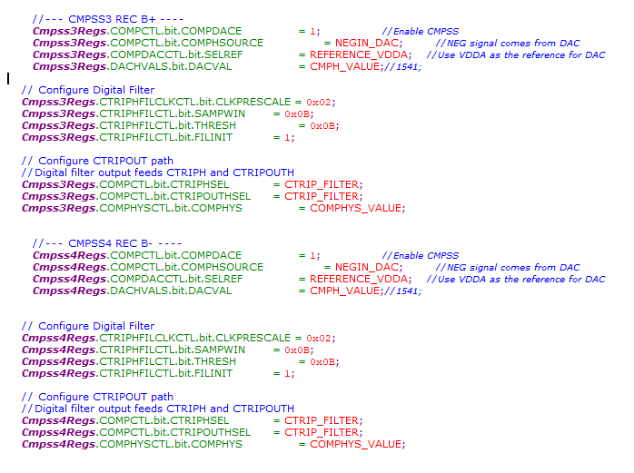
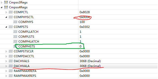
Customer tested with the same input signal, and feed to different CMPSS with the same configuration. They found the hysteresis performance varies among different modules. Take CMPSS3 and CMPSS4 as example, all the CMPSS configurations are the same. And the hysteresis of CMPSS3 behaves smaller than the setting, while CMPSS4 seems have no hysteresis, and this issue is more obvious when the DACVAL is higher, like 3068. Could you check for this? Thank you.
Hi Aki,
We haven't observed this. Can you provide some numbers of what you are seeing? Also provide scope shots. Thanks.
Hi Frank,
They used VDDA(3.3V) as the reference of CMPSS DAC, and 4x hysteresis setting, so the expected hysteresis voltage should be (48/4096)*3.3V = 0.03867V.
1) DACHVALA=3086, for CMPSS4, the measured hysteresis voltage is 0.002352V, which is lower than 10% of the expected value; for CMPSS3, the measured hysteresis voltage is 0.021756V.
2) DACHVALA=632, the result was better than the former one. For CMPSS4, the measured hysteresis voltage is 0.0294V; for CMPSS3, the measured hysteresis voltage is 0.03057V.
Hi Aki,
Thanks for providing the extra details. My suspicion is that they are experiencing noisy trips. A few questions:
1. How repeatable is their experiment? For instance, if they re-run about 10 times, what is the variation on the hysteresis they are measuring?
2. If they switch the COMPDAC reference to VDAC, do they see the same issue?
3. What source is driving the positive input?
I'm assuming the COMPDAC is being held steady and the positive input is swept. As an experiment, they can do the reverse: keep positive input steady and sweep the COMPDAC instead.
Frank,
Customer said the hysteresis error didn't change a lot with several tests done. They can not switch to the VDAC since the pin is occupied, and they used
DC regulated source as the positive input. They also tried to keep positive input steady and sweep the COMPDAC, and got the below test results:
CMPSS3 hysteresis error 3098-3068= 30LSB
CMPSS3 hysteresis error 3080-3068= 12LSB
Sorry, the results should be the hysteresis, not hysteresis error
CMPSS3 hysteresis: 3098-3068= 30LSB
CMPSS3 hysteresis: 3080-3068= 12LSB
Aki,
Sorry, what do the 30lsb and 12lsb refer to? Is this 2 runs on CMPSS3?
Frank,
Sorry for the typo. It should be:
CMPSS3 hysteresis: 3098-3068= 30LSB
CMPSS4 hysteresis: 3080-3068= 12LSB
which was almost matched with the former test results.
Aki,
No problem. Ok, what they are seeing is definitely unexpected. Can they provide the code snippet they are using to test the hysteresis? I just want to confirm it's similar to how we test it.
By the way, are they seeing this on a single F28075 unit or is this multiple units?
Aki,
If they are seeing it on 2 devices, then it's likely not a fluke. Below is a code snippet of how you can test the hysteresis. Had to take some stuff out so it might not compile but hopefully you get the idea. They need to use the latch with preferably non-zero filter settings. For the same signal on the positive input, they should run it multiple times to see how much cmpss_trip_code and cmpss_untrip_code varies. If they vary a lot, it means they can use hysteresis but can't use their setup to test hysteresis.
while(CMPSS_PTR[cmpss_ndx]->COMPSTS.bit.COMPHLATCH == 0) {// Sweep Down CMPSS_PTR[cmpss_ndx]->DACHVALS.bit.DACVAL--; DELAY_US(1); if(CMPSS_PTR[cmpss_ndx]->DACHVALS.bit.DACVAL == 0) break; EALLOW; CMPSS_PTR[cmpss_ndx]->COMPSTSCLR.bit.HLATCHCLR = 1; DELAY_US(1); EDIS; } if((CMPSS_PTR[cmpss_ndx]->DACHVALS.bit.DACVAL == 0)&&(CMPSS_PTR[cmpss_ndx]->COMPSTS.bit.COMPHLATCH == 0)) { cmpss_trip_code = 0xDEAD; // Fail } else { cmpss_trip_code = CMPSS_PTR[cmpss_ndx]->DACHVALS.bit.DACVAL; } while(CMPSS_PTR[cmpss_ndx]->COMPSTS.bit.COMPHLATCH == 1) {// Sweep Up CMPSS_PTR[cmpss_ndx]->DACHVALS.bit.DACVAL++; DELAY_US(1); if(CMPSS_PTR[cmpss_ndx]->DACHVALS.bit.DACVAL == 0xFFF) break; EALLOW; CMPSS_PTR[cmpss_ndx]->COMPSTSCLR.bit.HLATCHCLR = 1; DELAY_US(1); EDIS; } if((CMPSS_PTR[cmpss_ndx]->DACHVALS.bit.DACVAL == 0xFFF)&&(CMPSS_PTR[cmpss_ndx]->COMPSTS.bit.COMPHLATCH == 1)) { cmpss_untrip_code = 0xDEAD; // Fail } else { cmpss_untrip_code = CMPSS_PTR[cmpss_ndx]->DACHVALS.bit.DACVAL; } cmpss_hysteresis = cmpss_untrip_code - cmpss_trip_code;
Hi Frank,
Customer wonders whether it is necessary to use our code to test it, since they have swept the DACVAL for the same positive signal.
Anyway, for their convenience, could you please check whether the below code is correct(modified from yours)?
Take CMPSS3 as example.
EALLOW; Cmpss3Regs.COMPCTL.bit.CTRIPHSEL=CTRIP_LATCH; EDIS; while(Cmpss3Regs.COMPSTS.bit.COMPHLATCH == 0) {// Sweep Down Cmpss3Regs.DACHVALS.bit.DACVAL--; DELAY_US(1); if(Cmpss3Regs.DACHVALS.bit.DACVAL == 0) break; EALLOW; Cmpss3Regs.COMPSTSCLR.bit.HLATCHCLR = 1; DELAY_US(1); EDIS; } if((Cmpss3Regs.DACHVALS.bit.DACVAL == 0)&&(Cmpss3Regs.COMPSTS.bit.COMPHLATCH == 0)) { cmpss_trip_code = 0xDEAD; // Fail } else { cmpss_trip_code = Cmpss3Regs.DACHVALS.bit.DACVAL; } while(Cmpss3Regs.COMPSTS.bit.COMPHLATCH == 1) {// Sweep Up Cmpss3Regs.DACHVALS.bit.DACVAL++; DELAY_US(1); if(Cmpss3Regs.DACHVALS.bit.DACVAL == 0xFFF) break; EALLOW; Cmpss3Regs.COMPSTSCLR.bit.HLATCHCLR = 1; DELAY_US(1); EDIS; } if((Cmpss3Regs.DACHVALS.bit.DACVAL == 0xFFF)&&(Cmpss3Regs.COMPSTS.bit.COMPHLATCH == 1)) { cmpss_untrip_code = 0xDEAD; // Fail } else { cmpss_untrip_code = Cmpss3Regs.DACHVALS.bit.DACVAL; } cmpss_hysteresis = cmpss_untrip_code - cmpss_trip_code;
Aki,
Because what they are seeing is unexpected, we first have to make sure the procedure they are using to test hysteresis is correct and proceed from there. This is the reason for supplying the code for testing. The changes they have made to the code looks ok.
Please have them run this at least 10x and report the spread of cmpss_trip_code and cmpss_untrip_code.
Frank,
They has used the above code to test, and got the below results:
CMPSS3 hysteresis ranging from 32 to 50LSB
CMPSS4 hysteresis ranging from 5 to 12LSB
Could you help test it with F28075 and show our results to customer? Thank you.
Aki,
The variation they are seeing on CMPSS3, 18 LSB is very big which is making me question their setup. It seems to me their setup is not clean enough to measure this correctly. Nevertheless, I'll try this on the F28075 device and report back. You can expect a response latest by EOB Monday. Thanks.
Aki,
I'm still trying to secure a F28075PTPT part to test this on. We don't have one readily available locally at our site. Please give a couple of days for me to get one to test. Thanks.
Aki,
I was able to find a F28075PTP part to test this on. I'm not seeing any issues. For hysteresis 4x, CMPSS1-CMPSS4 are showing 41 to 45 LSB with 3.3v reference. This looks like an issue with their setup.
It's also interesting that they are seeing this on CMPSS4 because the inputs to CMPSS4; ADCIN14 and ADCIN15 go to all ADCs. This means ADCIN14 and ADCIN15 have increased load compared to the other pins which will be exacerbated when the ADCs are converting. Can you confirm that when they are measuring the hysteresis, no ADC is active.
For the purposes of debug and to minimize noise, can they enable the GPDAC and use it to supply the positive input of the comparator instead?
Also if you can, please forward the schematic for their system.
Hi Frank,
Thank you for the test confirm. I will check with customer for your proposal. Could you please share your test condition? Are you using GPDAC for the positive input? Which DACHVALS value your have tested?
Hi Frank,
Customer is actually using ADC in CMPIN4P when they are measuring the hysteresis of CMPSS4. Could you help also test it with active ADC? We wonder whether it is a main reason for this issue.
Aki,
GPDAC values used were 2048 and 3072. If they are using the ADC the same time as they are measuring hysteresis, then that is the reason. As mentioned, ADCIN14 and ADCIN15 see an increase load compared to the other ADC channels and thus anything that is driving them has to be sufficiently strong.
If the source driving ADCIN14 is not strong enough, whenever the ADC S/H cap closes, the voltage will droop and this droop will be reflected in the comparator trip.
Please have them forward the section of their schematic for this.
Aki,
Thanks, I'll review and get back to you. In the mean time, please have them check the hysteresis with the gpdac sourcing the positive input and no ADC sampling.
Frank,
Customer said it is difficult for them to wire the DAC as the positive input in their board. Is it possible for you to check the hysteresis performance with the ADCIN14 enabled? It can also validate our assumption. And do you have any suggestion for their AD sampling circuit ? Thank you for the support in this case for a long time.
Aki,
I unfortunately don't have bandwidth at the moment to check the hysteresis with the ADC sampling. If they can't use the DAC, they can use a battery with a potentiometer. Alternatively, they can also use the same setup as before but disable the ADC sampling when measuring hysteresis. Can you have them run the same test as before just with the ADC disabled?
As far as the schematic is concerned, the 2.2nF on the output of the opamp is very big. Why do they need that much capacitance?
Hi Frank,
The ADCIN14 is enabled with ADC-B during the CMPSS4 hysteresis test before. Now they tried to disabled the ADC-B sampling, the hysteresis increases to 20LSB, and when all the ADC sampling are disabled, the hysteresis is ranging from 44~48 LSB, which matches the datasheet. My question is that why the hysteresis is still lower when the ADC-B sampling is disabled. Is it due to the influence of the sample-and-hold circuits of other ADC modules?
Aki,
I'm glad to see that disabling the ADC sampling improves the CMPSS hysteresis.
I think the input network that they have is setup to do charge sharing but even with that, the capacitance they have on the output of the opamp is too big. Basically what this means is, when the S/H capacitor of the ADC closes to sample the signal, the majority of the current is provided by the 2.2nF capacitance which causes the voltage on input to droop. This droop in voltage is what is affecting the CMPSS trips. In-between samples, this big 2.2nF capacitance has to be fully recharged by the opamp.
If the ADC is sampling too fast and this full recharge doesn't happen in-between samples, the ADC will record an erroneous result. If the sample window of the ADC is big enough (in other words: ADC samples slowly), the ADC might not be affected as much since there could be enough time for the 2.2nF and the S/H cap to be fully charged.
For the CMPSS, these voltage droops will affect the trips. You can try to mitigate this by using the CMPSS filter so that a momentary trip will not affect the output of the filter. However, for this to work effectively, you will need to analyze the ADC sampling rate so you can tune the CMPSS filter accordingly.
They could also Spice their input network. Let us know if this is not clear.
Frank,
Thank you for the detailed explanation. They use sample frequency of 40K, with 13 CPU clock for the acquisition window.
Aki,
The most accurate way for them to analyze this is to Spice their input network. This way, they can see how much the voltage droops and for how long. They can then use this information to configure the CMPSS filter to ignore this window.
They can also look at it this way: Since they have confirmed for themselves that hysteresis is not malfunctioning, hysteresis is actually doing it's job. With hysteresis enabled, when the ADC samples the signal and droops the voltage on pin, hysteresis will prevent the comparator from untripping. Point is, the hysteresis amount didn't change but rather it's working as intended.
Let me know if i can mark this as resolved.
Aki,
I meant they should setup the filter window and threshold such that 1 or 2 momentary untrips does not untrip the output at the filter.