This thread has been locked.
If you have a related question, please click the "Ask a related question" button in the top right corner. The newly created question will be automatically linked to this question.
Tool/software: Code Composer Studio
Hi, I am using F28379D microcontroller. I am trying to generator Space Vector PWM (SVPWM) for 3 phase inverter. I am going through the control suite example D:\ti\ti control suite\development_kits\HVMotorCtrl+PfcKit_v2.1\HVACI_Scalar where svgen_mf is used to generate SVPWM. I have a few questions about this.
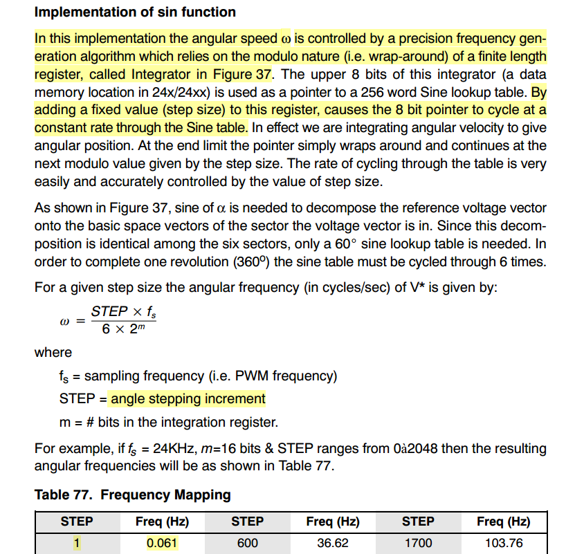
1. The attached image svgen_mf is screenshot of svgen_mf,h file in HVAC1 Scalar project. It uses step angle to determine the sector number. v.StepAngle = _IQmpy(v.Freq,v.FreqMax); Why is freq and FreqMax multiplied here? In the svgen_mf module (in spru485a.pdf), STEP is used to determine angular frequency (Screenshot attached). Can you please give an example code where this approach is used to determine angular frequency?
If my switching frequency is 20kHz, mains frequency is 60Hz, then how do I provide the angular frequency w in my code?
2. This project takes Freq and Gain from Voltage/Hertz Profile (VHZ) module as follows:
svgen_mf1.Gain = vhz1.VoltOut;
svgen_mf1.Freq = vhz1.Freq;
I do not intend to use VHZ module. How do I provide this varying angular frequency in my program?
3. In three phase inverters, which macro is better for SVPWM generation, svgen_mf or svgen (which is in dq)?
Thanks.
1. Some of the variable names are not logical and leads to this confusion. This is a very old code. You can look at v.FreqMax as the max step angle corresponding to max sine frequency. v.Freq is the frequency of sine wave in normalized for (0 to 1pu). This multiplication helps to get the incremental step angle to step through the sine LUT at this given v.Freq.
2. You will have to figure out a way after better appreciation of how these modules work.
3. I would consider using SVGENDQ
Thank you Ramesh. Your answer resolved half of the confusions I had. Still I would like to know how to proceed with part 2 of my question. Part 2 was
2. This project takes Freq and Gain from Voltage/Hertz Profile (VHZ) module as follows:
svgen_mf1.Gain = vhz1.VoltOut;
svgen_mf1.Freq = vhz1.Freq;
I do not intend to use VHZ module. How do I provide this input frequency to my program. As per my understanding, v.FreqMax is a constant (v.FreqMax as the max step angle corresponding to max sine frequency) and v.Freq will be a variable. But I don't understand how to provide this input (v.Freq) to my program?
Moreover, why is it suggested to use svgen_dq instead of svgen_mf?
Thanks,
Halima
Halima,
As I said before, you need to review the working style of the example to get a handle of how things work. Try it out on the eval kit.
svgen_dq is suggested because it is used in closed loop FOC.
I hope you have figured out the issue based on available info. Since there is a long silence, am closing the thread. If you have any related queries, post it within 30 days to reopen the thread otherwise create a new thread.
Hi Ramesha,
As you suggested, I worked on svgendq and got my SVPWM working.
I actually have to implement other SVPWM techniques using svgendq.h. I have full understanding on SVPWM concept but there is some vagueness in the code.
Can you please answer this question for me or connect an expert with me for this problem if possible? I have read its theory here http://www.ti.com/lit/ug/spru485a/spru485a.pdf but still there are some confusions.
Attached here are the svgen.h and svgendpwm.h codes. In svgen.h, 2 switching phases and 2 zero states are used in each sector, for example, for sector 1 the sequence would be 0127-7210.
However, in svgendpwm.h, 1 one the phases is clamped on either positive or negative DC rail and 2 switching phase and one zero state is used in each sector, for example, for sector 1 the sequence would be 012-210. In svgendpwm.h code, for sector 1, phase a clamped to positive bus (i.e. Ta=0). and for sector 6, phase c is clamped to negative bus, but I don't see how does it work in the code, how do we have same duties for sector 1 and 6? The code snipped from svgendpwm.h is as follows:
if (v.VecSector==1 || v.VecSector==6) \
{ \
v.Ta= 0; \
v.Tb= v.tmp3; \
v.Tc= v.tmp2 ; \8546.svgen.hsvgen_dpwm.h
}
The people that wrote this are not around. But the concept is this. The method you refer to is about difference pwm, to reduce switching losses. The voltage seen by the three phase load wrt its neutral is dependent on how the three inverter outputs are relative to each other. In this case, a common mode voltage is added to each of the three phases such that the most dominant phase voltage is taken to the rail level so that that phase wont have to switch. A same amount of voltage is added/ subtracted to each of the other phases depending on the sector.
Let us say the calc value of time are
Ta = x
Tb = y
Tc = z,
then from a three phase load standpoint,
Va = x-x = 0
Vb = y-x = tmp3
and Vc = z-x = tmp2
will give the same phase voltage wrt the load neutral. However, this ensures that phase A wont switch and therefore there is a saving on the switching losses.
If the issue is resolved, let us know so we can close the thread. thanks.
I am closing the thread. If you have any further queries, you can post again within 30 days to reopen this or else create a new thread. Thanks.